

Operating power plants requires a detailed understanding on how different systems of the plant interact with each other, how water and steam are used to transfer energy and the limitation of control loops. This simulator allows you to try to start up the Chernobyl RBMK reactor, sync it to the grid and experience the complexity of power plant operation.
This project is currently in development It is NOT FINISHED. Do not expect a working product. You can download the project on Github. A more convenient way of downloading and running will be provided as the development progresses further. Expect things not to work as desired and some systems are still not finished.
This simulator focuses on operating the thermal systems of the power plant and is simplified in a way that it can be handled by one person.
It features:
- Two steam drum separators (instead of 4)
- Simplified reactor with 5 automatic, 28 manual and 4 short control rods (instead of 170).
- One turbogenerator with steam reheater
- Mnemonic displays inspired by the actual control room
- Convenient line plots to monitor measurement time series
- Accident sequence (prompt neutron excursion) possible
- Nasty reactor dynamics
Motivation
In 1998 there was a simulation called “Chernobyl: The Legacy Continues” which is actually a simplified, working power plant simulation. I used to work in coal fired power plants before and after my engineering graduation and had the chance to actually work on real control systems engineering, that simulator got my attention and I even wrote a startup manual for it. After switching to food machinery manufacturing I was able to finally deep dive into coding and got the skills to work on a successor to this masterpiece.
As I’m benefiting much of open source software here and many people provided valuable information free of charge, I decided to release this as free and open source software.
Usage
I recommend to run the simulator on 2 or even 3 1080p monitors. This actually gives you a real power plant control room feeling at home.
The control panel will contain all windows that can be used to operate and view the simulation. For supporting multiple monitors, additional control panels instances can be opened.
It is planned to have networking support for better distribution of panels to multiple operator stations, also saving user defined presets shall be implemented at some point.
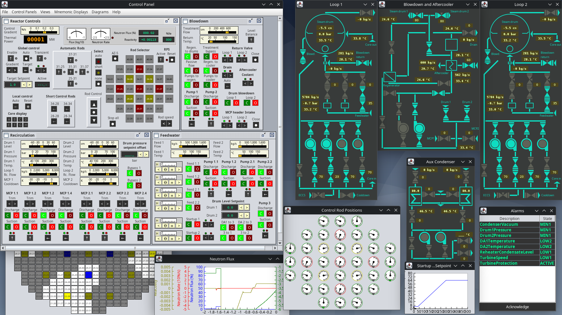
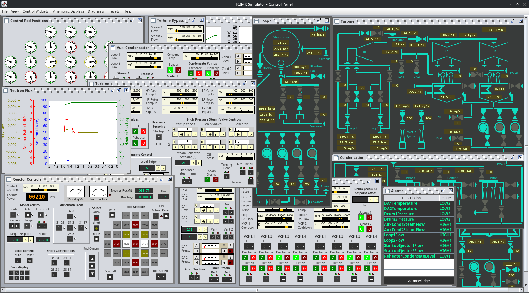
Control Panel
Starting the simulation will open one panel with the reactor controls widget shown. Using “Presets” – “Full Control Panel”, all operation control panel widgets can be displayed in that active window.
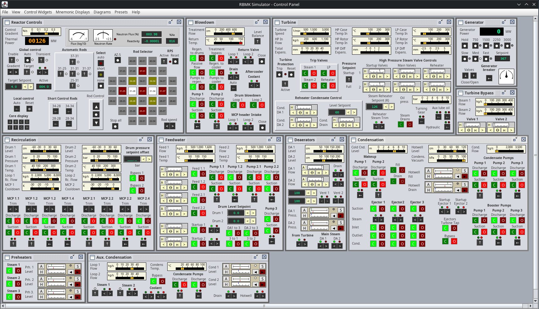
The individual control panel widgets can be rearranged individually or a preset as shown can be used. The layout is kept in a retro style as we’re dealing with a plant that was build in year 1979.
There is a certain way on how the control panel is operated. I tried to mimic the behavior of such control panels with the elements that are available on modern computer programs. Some buttons and switches will not do anything if some prerequisites are not met. Switches need to be turned again to their “on” position if something was shut down, things will never turn themselves back on.
Some controls have tooltips with a description.
Valves
Some valves can be opened or closed only, those are operated with green and red buttons. The button with the corresponding end position will light up as soon as the valve is open (red/in Operation) or closed (green/ready).

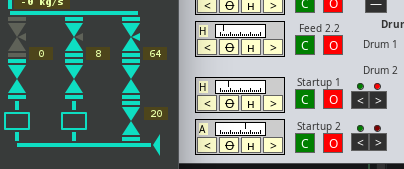
Other valves might be controlled by a control loop output (level control), there is a widget with four buttons for such valves. The indicator scale shows the current valve position. The two middle buttons switch between manual and auto mode, the outer buttons directly control the valves position. Active control loops are indicated with a lit up triangle on the mnemonic display. The valve control widget shows “H” on manual and “A” on auto mode.
Valves which can only be controlled manually have a smaller switch with two buttons and a red and green indicator above the switch. Their position has to be obtained from the mnemonics.
Control Loop Widget
Sometimes, multiple valves do the same thing and have the same setpoint value. In other cases, there might be a simple control loop with only one single valve and a setpoint just for that one valve. Such control loops can be controlled by a control loop widget.

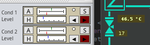
The upper gauge shows the current value (green) and the setpoint value (red) with the same scale. The lower gauge shows the current valve position, or any other output elements value. The A and H buttons toggle between auto and manual mode. Pressing the red “S” button will toggle setpoint mode. The up and down buttons do control the valve manually or do a manual override. If setpoint mode is active, those buttons are used to modify the setpoint instead of the valve position.
Switching Pumps
Centrifugal pumps have a valve on each side (suction and discharge). To turn on a pump, the discharge valve has to be closed. This ensures no reverse flow could ever turn the pump when switching the motor on. This is enforced in the simulator. Each pump on the control panel can be found on a mnemonic display showing the current pump state. The suction valve usually remains open and has to be opened before turning on the pump.

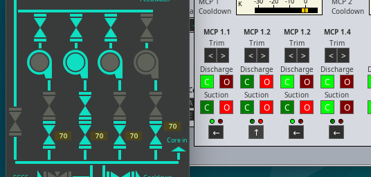
A pump is ready to be turned on when the outline glows. Its startup sequence is indicated by a slight glow, a running pump is indicated with a glowing inner circle. Do not open the discharge valve before the pump is running.
Reactor Operation
There are a total of 28 manual control rods, 5 automatic control rods and 4 short rods from below. Rods can be selected with the rod selector and moved using the rod control buttons. Note that the short control rods (yellow) have their direction reversed. Manual (gray) and automatic (red) control rods are inserted from the top so the reactivity increases with them going up out of the core. The yellow rods need to be moved downwards to increase reactivity.

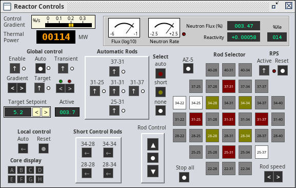
The global control has a target setpoint and an active setpoint for the rod control loop. That loop setpoint ramps up to the target setpoint when the target and transient switches are on and the ramp can be set with the gradient switches. That allows to pause the transient.
Global control will move the selected auto rods (red) trying to keep the active setpoint value. You need to get the reactor in a state where this works, it is your job to pull out enough manual rods (gray) or push them back in to keep the auto rods in operating range.
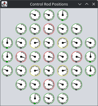
The position of each rods can be viewed using the selsyn gauges on the control rod position window.

Pay attention to both the red and the green lights on top of the override switch of the global control, those do indicate that the automatic rods are reaching the top or lower position (an alarm will also be fired in such cases).
File – Set core only mode will disconnect the reactor model from the thermal layout so nothing heats up and you can raise the neutron flux to 100 %. That also means no voiding feedback from the thermal model. Use this to get yourself familiar with the rod controls.
Mnemonic Displays
To get a view on the current plant state, so called “mnemonic displays” were used in the control room of the Chernobyl operating control room. The simulator features schematic views which are heavily inspired by those displays.
The mnemonics windows can be added to the control panel, there is also one preset that displays all of them on a 1080p monitor.
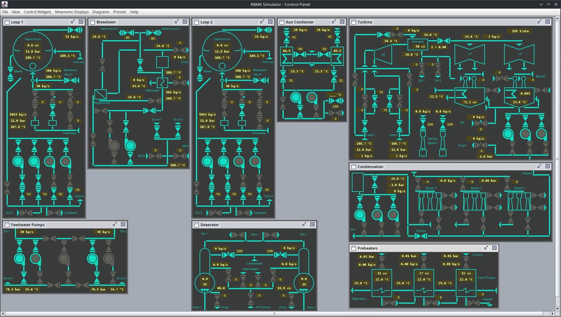
To make the usage more convenient, measurement values are displayed directly on the mnemonic displays.
Alarms
Some values are attached to alarms which are triggered when above or below a certain level. There are four alarm thresholds available (not all of them need to be mapped to a vale) for each direction. The first two are considered warning and there is no consequence if they are appearing. The second two alarm thresholds are always connected to a certain event (valve operation, pump shutdown, …).
For high values there is:
- HIGH1 – warning only
- HIGH2 – warning only
- MAX1 – Triggers an event
- MAX2 – Triggers an event
For low values there is:
- LOW1 – warning only
- LOW2 – warning only
- MIN1 – Triggers an event
- MIN2 – Triggers an event
Some elements also have a safety override implemented that prohibits opening or closing valves or switching on certain pumps.
This is not only done to ensure the plant’s integrity, it is done because the modeling engine does not allow certain states and would otherwise crash.
Protection Systems
Reactor and Turbine both have a Reactor Protection System (RPS) and a Turbine Protection System (TPS).

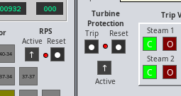
Those systems ensure that operation of the reactor and the turbine is only possible in valid operating regimes. The RPS will force all control rods into the core, immediately shutting the nuclear chain reaction and the TPS will shut down fast closing trip valves.
To trigger the RPS action manually, you can press the AZ-5-Button which is the equivalent of a SCRAM button. The TPS can be triggered by pressing the Trip-Button.
Reactor Startup and Sync to grid
As I want you to figure out how things work, here are just some rudimentary hints on how the simulator has to be operated.
- The RPS can be disengaged when certain alarms are no longer present. The simulator starts with a shutdown state after some repairs and maintenance were done, everything is cooled down.
- Make yourself familiar with the blowdown and cooldown system which is used to remove decay heat and has to be switched to a state where the reheater is used.
- To startup the reactor, pull out 4 to 6 manual control rods to increase reactivity. Use the red auto control rods to manually get to a positive reactivity of about +0,001. Wait and watch the neutron population grow as the flux log gauge goes up. Reduce reactivity if neutron rate is too sharp.
- The auxiliary condensation is used to condensate steam during startup and shutdown when no condenser vacuum is available. Use them for initial startup to control pressure.
- Start evacuation of condenser and spinning up the turbine with 15 bars on 140 MWth. Sync to grid at 50 bar on 326 MWth roughly.
- The turbine startup valves are used to control the turbine speed for startup. The main valves are used to control the pressure in steam drums. Startup needs about 10 kg/s. Reheaters are not in use during startup.