Lots of inventions have been made in the past centuries to utilize the hydraulic fluid to create an oscillating piston movement. There are multiple publications [1-5] to point out similarities and classify the working principles. This page tries to give an overview about the known hydro-mechanic machines and explain the way they work.
The main difference between hydraulic and pneumatic percussion drives is the lack of a compressible fluid. This sounds obvious but makes the way of constructing such a device much more challenging. While pneumatic percussion drives make explicit use of the compressibility of the operating gas, hydraulic drives have no way of accessing such a part. The increasing hydrostaic pressure in deep wells are also challenging and make the use of pneumatic elemts nearly impossible.
There are multiple concepts to drive a hammering piston by hydraulic fluid. It is reasonable and common to classify them by the force action transmission and the dynamic behaviour of the hydrauilc mechanical system. That way, hydraulic hammers can be classified into those mechanisms:
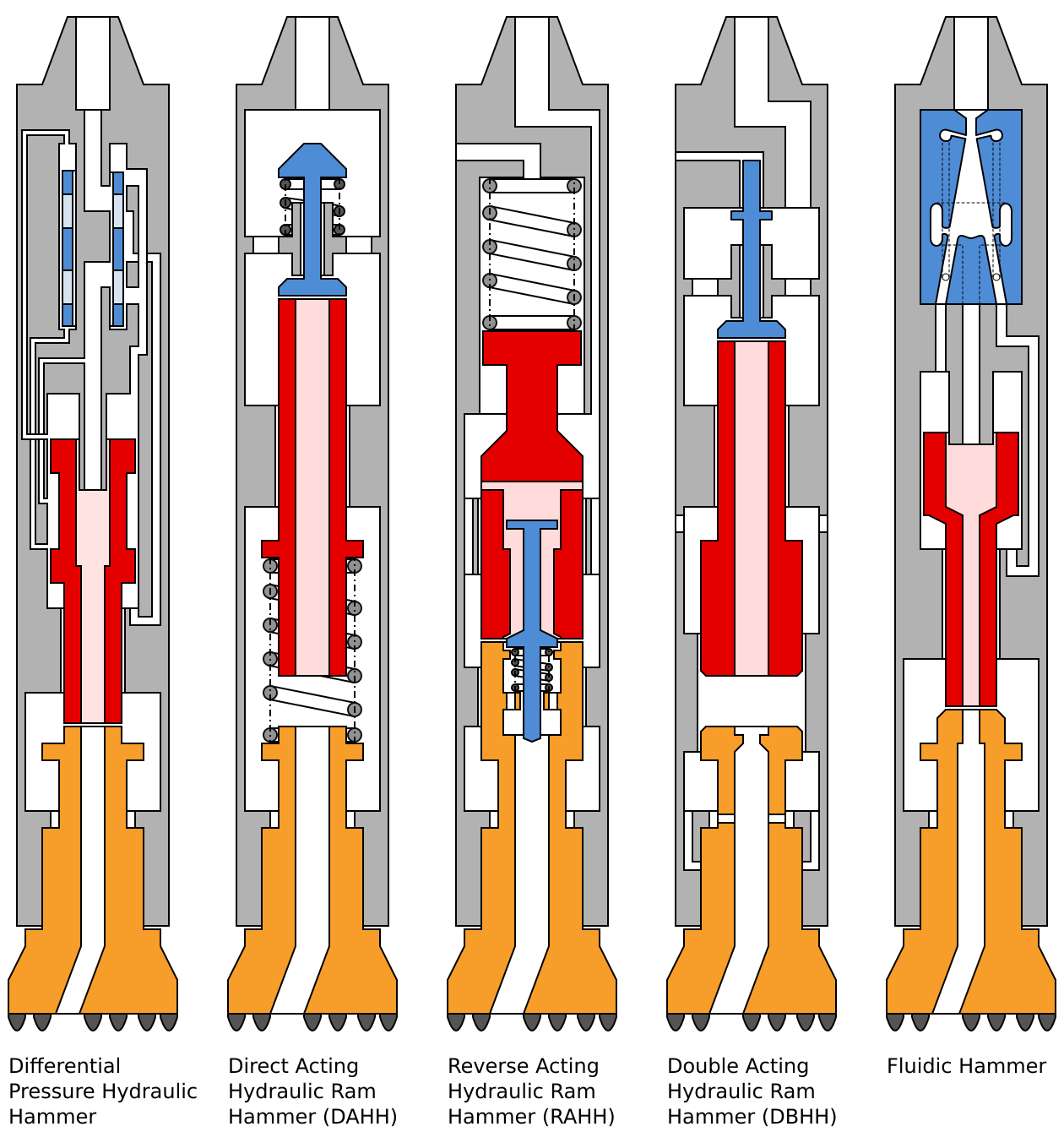
- Differential pressure hammer with permanent active piston areas and fixed displacement [5],
- Hydraulic ram hammers which have an open flow path through the whole hammer, interrupting it for a water hammer effect. Those can be further subclassified [1,2, 6] as
- Direct Action Hydraulic Hammer (DAHH),
- Reverse Action Hydraulic Hammer (RAHH),
- Double Action Hydraulic Hammer (DBHH),
- Hydraulic systems with energy dissipation,
- Fluidic hammer using a fluidic oscillator based on the coandă effect
Futhermore there are also some concepts of split systems to drive the percussion hammer, using pdm drives to drive a hydraulic pump or generate electricity for magnetic actuators [7].
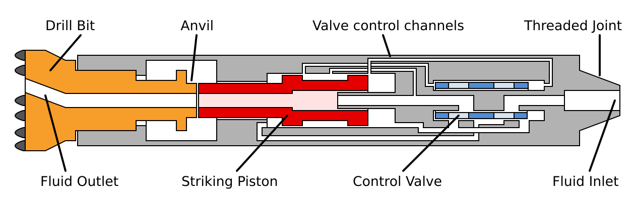
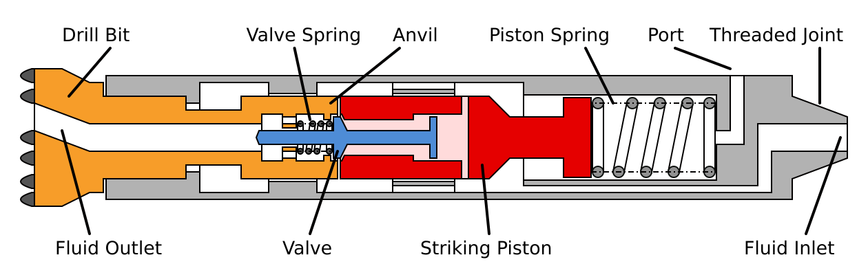
Differential Pressure Hammer
This concept uses the pressure differences on opposing surfaces to move the striking piston and valve masses. Typically it is also used with high pressures to keep flow low and reduce the amount of hydrauilc inducted pressure peaks. As mass displacement is done by the hydraulics, there is a correlation between part movements and hydraulic flow.
It is named by the different pressures moving the masses, the term also suits the fact that the pressure drop over the hammer is usually very high compared to the hydraulic ram hammers. Most of todays available hydraulic DTH hammer systems work in such a way.
The striking piston is moved by putting the hydraulic fluid to one side of the piston and opening the other side to the fluid outlet. The striking piston will open channels to switch the hydraulic valve as it reaches its top or bottom position, switching the main hydraulic channels and reversing its movement.
Even if this seems to be simple and the animation is looking fine, it is acutally not as simple as it is shown here and would not work if it is built like that.
The hydraulic power consumption is mainly driven by the pressure which the mass puts up as a reacting force to the hydraulics when it is getting displaced. Even though this is acausal, it is still sufficient to descripe the basics and classifications.
Hydraulic Ram Hammers
Hydraulic Ram Hammers operate by having an open flow path which allows a continuus flow through the whole hammer from fluid inlet to outlet ports. By using a valve to close this path, the hydraulic inertia will cause the pressure to inrease very fast, creating a so called water hammer effect. This is similar to the hydraulic ram pump.
Hydraulic power from the pumps is therefore used to accelerate the water column in the drill string. The water column acts as a energy storage which is accelerating the hammer piston by momentum transfer and gets accelerated by the pumps itself. The operation of hydraulic ram hammers is depending on the drill string length: There will be dampening effects towards the pumps, a more steady flow and pressure will be at the pump the longer the drill string will be.
Depending on the use of compression springs on the striking piston or other compressible elements, those hammers can be subclassified by the hydraulic action as direct, reverse or double. This classification was introduced by Ясов [1] in Russia:
- Direct Action Hydraulic Hammer (DAHH) which use hydraulics to accelerate the piston for the hammer stroke and retract it with a spring,
- Reverse Action Hydraulic Hammer (RAHH) which use a spring and/or gravity for hammer stroke and use a hydraulic retraction of the hammer piston,
- Double Action Hydraulic Hammer (DBHH) which use the hydraulic water hammer for hammer stroke and also use hydraulics to retract the hammer piston.
Direct Action Hydraulic Hammer
The Direct Action Hydraulic Hammer seems to be the simplest of all mechanisms to create a hydraulic percussion drill, since its invention in the early 1930s it was subject to many research projects for that reason.
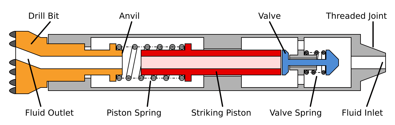
As the striking piston is in his striking position, hydraulic fluid can flow thorugh the hammer. The piston spring is pushing the striking piston towards the valve, when the valve is reached, the water flow is interrupted. The water hammer occurs and the pressure moves the piston and bit together forward towards the anvil. The valves movement is limited so after some distance it will stop. The flow path is then open again, the piston continues until he hits the anvil.
Even though this concept looks very easy, the hydromechanical dynamic system is hard to describe. The momentum transfer can force the hydraulic fluid to stop while the piston is moving afterwards, creating a steam bubble with cavitation damages. Also the use of compression springs is not applicable due to the low lifetime under these circumstances.
The Hammer of Cyphelly from TU Clausthal [3] which was developed for the KTB drilling project [8] is working in such a way (even though it is build different). Also two prototype hammers at GZB [9] and two prototype hammers for a core drill system from DSK [10] can be classified as DAHH. Those Hammers were also used in the USSR in the 1940s.
Reverse Action Hydraulic Hammer
If the hydraulics are only used to lift the striking piston off the bit, the concept is called a Reverse Action Hydraulic Hammer. The energy for the striking movement towards the bit is then stored in gravity and/or a compression spring, the hydraulics can flow through the hammer during the downstroke.
This concept was patented by Harry Pennington in 1927 [11]. The striking piston gets lifted by the hydraulic ram and the energy is stored as potential and spring energy.
When hitting the anvil at the end of the downstroke, the valve is getting pushed into the drill bit and remains there due to the pressure that is build up when it is closed. The striking piston is then lifted hydraulically as the back side is connected to the low pressure in the annulus. The valve remains closed on the bit as the pressure keeps it closed against the valve force. At a certain position, the piston will lift the valve, the pressure will drop as the path through the hammer is now open and the valve spring pushes the valve against the striking piston, keeping it open. The hydraulic fluid can now freely flow through the hammer, the striking piston will now be accelerated by the compressed piston spring.
Double Action Hydraulic Hammer
Both piston movements can be done hydraulically, also using the water hammer effect for the downstroke. This is then classified as a Double Action Hydraulic Hammer. Due to the lack of springs for piston movement, this concept offers a higher tool lifetime. It is also possible to move the valve with hydraulics.
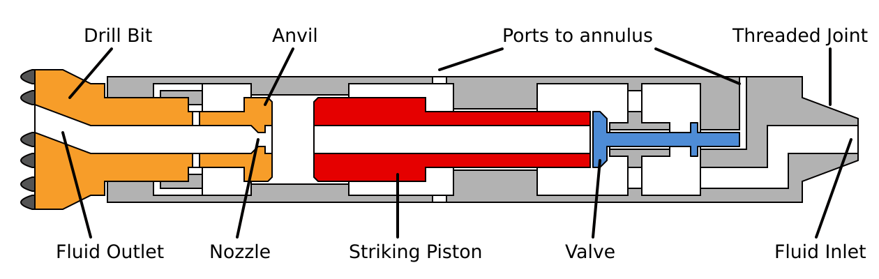
Using a small orifice on the anvil and having a bigger surface on the piston front, a pressure drop will push the striking piston upwards towards the valve. To achieve this, the back side of the piston is connected to the annulus.
The main advantage is the lack of springs. Usually, springs will not last the desired tool lifetime and tend to fail. The piston needs to push the fluid through the small nozzle in the anvil on downstroke which is also a loss of energy.
The Pen-Rock/Hammergy OPTI-Hammer [12, 13], the YZX127-Hammer [6], a prototype hammer from GZB [9] and the ZW1 from TU Clausthal [3] can be categorized as such a device.
Hydraulic Systems with Energy Dissipation
The end of the drill string presents a kind of rough hydraulic power supply: Due to the high hydraulic inertia, water hammer effect will occur and is used with the concepts described above. However, this also means some challenges as pressure peaks can get extremely high. Placing a small nozzle as energy dissipator parallel to the hammer mechanism changes the whole system and the dynamics. Those percussion drills work like the differential pressure drills, a valve is swichting the pressures on surfaces of a striking piston.
Some times these mechanisms get classified as double action hydraulic hammers [4]. Depending on the definition this is correct but here we’re going to classify them different as they do not use the water hammer effect like the initial concepts of Ясов.
The Novatek Mudhammer [14] and the YDC-Hammer [15] of PetroChina Research can be classified as such.
Fluidic Hammers
Using a fluidic element, fluidic hammers are utilizing a fluidic switch to implement the oscillation. A fluidic element is based on the coandă effect, describing the ability of flow streams to follow a contour

flow inside the fluidic element will attach to one side and apply a pressure either on the upper or lower surface of the striking piston. As the piston hits the upper or lower position, a shock wave will travel through the feedback channels back to the switching nozzles and switch the fluid flow to the opposing surface, where it will attach again, moving the piston in the other direction.
Some notable examples are the SC 54 Core Drill [16], the Efflux Hammer Prototype [17] and the KSC127 from CCSD [6].
References
[1] В. Г. Ясов, Теория и расчет рабочих процессов гидроударных буровых машин. Moskau: Недра, 1977, p. 153.
[2] Y. Melame, A. Kiselev, M. Gelfgat, D. S. Dreesen, and J. Blacic, “Hydraulic hammer drilling technology: Developments and capabilities,” 8, p. 11, 1997.
[3] G. Zhao, “Entwicklung und Optimierung eines hydraulischen Bohrhammers,” Technische Universtität Clausthal, Clausthal-Zellerfeld, 1998.
[4] X. Huang, G. Hu, Q. Meng, and X. Zheng, “Development Status of Hydraulic Hammers and Development Trends of Hydraulic hammers Used in Oil and Gas Well Drilling,” Electronic Journal of Geotechnical Engineering, no. 21, pp. 5453–5464, 2016.
[5] J. D. Linke and R. Bracke, “Systemvergleich und Wirkmechanismen verschiedener fluidbetriebener, hydraulischer Imlochhämmer,” Hochschule Bochum, Bochum, 2013.
[6] D. Wang et al., The China Continental Scientific Drilling Project. s.l.: Springer-Verlag, 2015, p. 362.
[7] R. Zimmermann, F. Lehmann, and M. Reich, “Entwicklung von Bohrhämmern für die Tiefbohrtechnik,” in Der Geothermiekongress 2015, 2015.
[8] B. Engeser, “Spülungsbetriebener Bohrhammer,” Das Kontinentale Tiefbohrprogramm der BRD, Bohrtechnische Dokumentation, Hannover, p. 4, 1996.
[9] R. Bracke and V. Wittig, “Entwicklung eines rotierenden, hydraulischen DTH‐Hammer‐Bohrsystems für Tiefenbohrungen mittels Coiled‐Tubing‐Bohrgestänge,” Geothermiezentrum Bochum, Mar. 2016.
[10] DSK, “Entwicklung eines Seilkernsystems mit hydraulischem Imloch-Bohrhammer für Kernbohrungen,” p. 45, 2002.
[11] H. Pennington, “Well Drilling Apparatus,” US1892517, 1927.
[12] P. A. Vatne, “Høyfrekvent væskedrevet perkusjonsboring i harde formasjoner,” NFLB Høstkonferansen. Kristiansand, p. 20, 2014.
[13] P. A. Vatne, “A fluid percussive driven, high frequency percussion hammer for drilling in hard formations,” 2015.
[14] D. S. Pixton and D. R. Hall, “Development of a New-Generation Mud-Driven Dowhole Hammer System,” GRC Bulletin, vol. August 1995, 1995.
[15] X. Huang, G. Hu, Q. Meng, and X. Zheng, “Impact performance optimization of a YDC valve-type double action hydraulic hammer,” Natural Gas Industry B, vol. 5, no. 5, pp. 425–433, Oct. 2018.
[16] J. Weltermann, “Untersuchung der Wirksamkeit hydraulischer Bohrhämmer zur Optimierung des Hartgesteinbohrens,” Technische Universtität Clausthal, Clausthal-Zellerfeld, 1990.
[17] Z. Jian and J. Shang, “A Type of Advanced Mud-Hammer Applied to Oil Drilling,” in SPE Asia Pacific Oil and Gas Conference and Exhibition, 2005, p. 3.
good explanation. Do you have animation for double action hydraulic hammer?