Mankind is using hammer and chisel for rock-destruction since the stone age until today. This article shows which ideas and inventions were made in the past to put the hammering into an integrated hydraulic downhole drilling machinery.
There are two techniques which came together: Deep drilling for oil, gas and water wells as well as blasthole drilling in tunneling and mining during the industrial revolution.
Pneumatic Rock Drills in the 19th century
The first steam powered rock drills were invented in the 1850s, until then, tunneling was mainly done by hand. Those inventions were made to drill blastholes. During the construction of the Hoosac tunnel, some new machines like air compressors and air driven percussion drills were used the first time [1].
The hammer drill by Ingersoll in 1871 is often mentioned as a milestone [2,3] in percussion drilling. A chisel is accelerated into the hole and turned automatically. The apparatus was small enough to be transported by workers and had an automatic feed [4].
The idea to construct a valveless hammer drill can be dated back to 1872 [1] as C. J. Ball came up with a patent which used the piston as a valve: When reaching a certain position, the piston will open channels connecting the surfaces of the piston to the exhaust and the fluid supply. This will put pressure to one side and release the pressure from the other side. As this accelerates the piston, it will close the channels and the fluid will expand, still accelerating the piston until it reaches the other side, reversing the pressures. This concept is still used in pneumatic down-the-hole (dth) drills but cannot be used for hydraulic dth drills, as the expansion is part of the mechanism and not available for hydraulics.
Well drilling in the 19th century
Even until the beginning of the 20th century, well drilling in hard rock was done by cable tool percussion drilling: A chisel mounted on a cable is dropped into the borehole and pulled up again. This method is known since thousands of years and still used in developing countries.
For drilling soft rocks, fishtail drag bits were used in rotary drilling.
There are some inventions at the End of the 18th century which proposed a drive mechanism at the end of the drill [5] driven by the drilling fluid, like the turbine drive for diamond drill bits from 1873 by Christopher G. Cross [6].
1900: Hydraulic Ram Drill by Wacław Wolski
In 1900, Wacław Wolski improved cable drilling by using a hydraulically driven chisel at the end of the drill string. This was the first hydraulic down the hole percussion mechanism [7-9] also called the “Ram of Volsky” [5].
The mechanism works like a hydraulic ram: If the velocity of the drilling fluid is high enough, it will close the valve and the pressure built up will shoot out the chisel. To dampen the water hammer effect, a small gas-filled cavity is placed before the mechanism. For greater depths this was then replaced by a spring-loaded piston due to the increasing hydro static pressure [11].
1908: Invention of the roller cone drill bit by Howard R. Hughes
Howard Robard Hughes invented the roller cone bit om 1908, this was the breakthrough for rotary drilling and made the later invention of the tricone carbide insert drill bit possible. Percussion drilling now needs to have significant advantages over this technology to reach a breakthrough. This is the main reason why hydraulic dth percussion drilling still has not evolved over rotary drilling.
1927: Hydraulic percussion drill of Harry Pennington
Harry Pennington patented his hydraulic percussion drive in 1927. The drilling fluid is lifting the hammer piston, it is accelerated towards the anvil by a spring and its gravity. Button Bits were not invented at this time so the drill bit was a flat chisel.
As the hammer piston hits the anvil, it will close the valve placed inside the anvil. This will lift the piston as the hydraulic pressure builds up inside the tool until the hammer piston will lift up the valve. The valve will be held open by a spring after it was lifted a bit, the lifting of the valve will cause a pressure drop. As the pressure dropped, the hammer piston will be accelerated towards the anvil by the spring and by gravity, hitting the anvil and closing the valve again.
1930: Hydraulic ram hammer of John A. Zublin
In 1930, John Adolphus Zublin patented a fluid driven hammer mechanism [13]. The patent consists of multiple mechanisms to convert the hydraulic energy to a percussive motion and some possible piston retraction concepts.
The hammer piston is moved by a spring (43) towards the valve (35), this will close the fluid passage, accelerating valve and piston by using the water hammer effect. The valve displacement is limited by a small rod (61), so the passage will be opened and the hammer piston continues to hit the anvil.
The patent also mentions a piston retraction without any springs, using different area sizes and connecting the hammer piston back area to the outside of the drill.
By using a small orifice inside the flow path at the anvil (197) a pressure drop will occur depending on the flow. As the back surface of the piston (184) is connected to the ring annulus, the pressure will press against the front surface (186) will push the hammer piston upwards, against the fluid flow.
1946: Bassinger Tool
Ross Bassinger was developing hydraulic percussion tools in the 1940 with his company “Bassinger Tool Company”. The valve was placed around the hammer piston instead of being a valve head. His son Grey Bassinger was continuing his developments afterwards. Bassingers tools were able to gain advantage over rotary drilling [14].
The rate of penetration was about 30 % higher while drilling in Oklahoma [16]. Bassinger Tools were also used by shell for multiple wells in Alberta [17].
The use of roller cone bits was challenging due to the impulse transfer though the bearings and the use of regular teeths [18]. Button Bits were still not invented in the 1950s. Various drill bits have been tested, best results were obtained using a roller cone bit with sleeve bearings instead of ball bearings [16].
Using a rubber coating the abrasive wear of the hammer piston could be reduced so the hammer could be operated up to 14 hours. The rate of penetration was signtificantly higher compared to rotary drilling, for example the ROP in anhydrite and gypsum rock in canada was about 2,4 m/h compared to 1,7 m/h with rotary drilling [19, 20].
1968: Hydraulic Percussion Drill of Pan American Petroleum
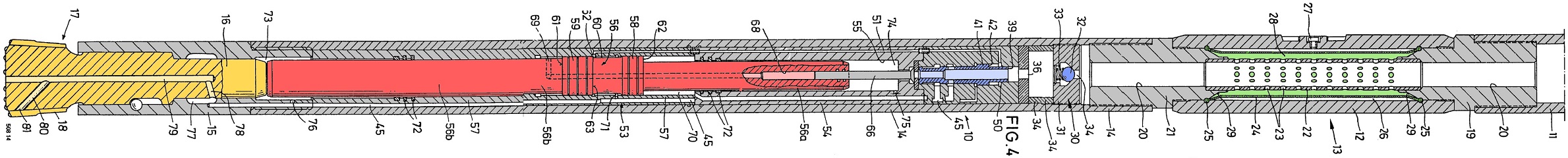
The invention of a new kind of hydraulic percussion drill at Pan American Petroleum Corp. (later known as Amoco, then BP) by Renic P. Vincent in 1968 was another milestone. Using 7” and 11” tools they were able to increase the rate of penetration about three to five times compared to rotary drilling [21].
The 11” tool had a length of 2,3 meters and a hammer piston mass of 400 kg. Still, roller cone bits were used as drill bits [23].
1983: Downhole Hammer of Klemm
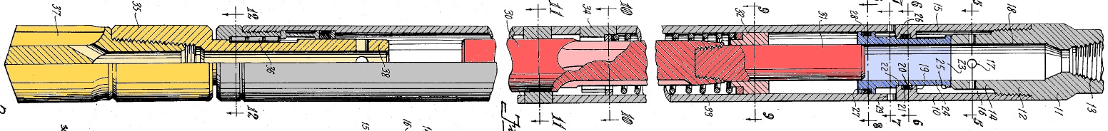
Günter Klemm patented a hydraulic driven DTH drill in 1983. It used a valve to switch the hydraulic pressure driving the piston. This can lead to pressure peaks so the patent also contains a gas based dampener.
The striking piston (56) has different surface areas. The front side (61) is always kept under pressure while the back side (62) with the bigger surface is switched between pressure inlet and the outlet to the drill bit.
1987: Development of Wassara Water Hammer
In 1987 Per Gustafsson patented the fist version of the Wassara drill [25]. Hydraulic DTH Drilling was investigated by Atlas Copco at that time, the Patent was sold to G-Drill and G-Drill was sold to LKAB who then founded the Wassara brand [26]. Today, Wassara is producing and selling a hydraulic driven, water powered down the hole hammer drill.
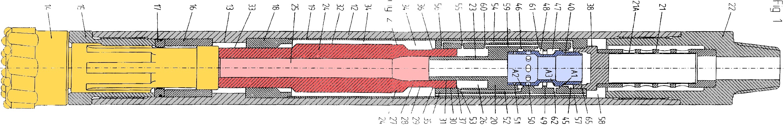
Water powered percussion drilling was developed to mass production with this technology by Wassara, the tools are now wide spread in mining and construction works, making explicit use of all the advantages of having an hydraulic fluid for drilling: Using water instead of air prevents dust, this is a significant advantage in mining. The power consumption compared to air DTH drilling is significantly lower [28]. Due to the lack of expansion on lower pressures, the velocity in the ring annulus is much lower compared to air drilling, making it possible to use the tool chassis as a stabilizer for straight, long holes.
The tool was used for shallow geothermal drilling at GZB in Bochum for borehole heat exchangers. Rotary drilling in limestone had an ROP of about 25 m/h and dropped to 5 m/h in sandstone [28]. However, using the Wassara tool in the same geology the ROP was about 45 m/h and the tool was not any slower when encountering hard sandstone formations [29].
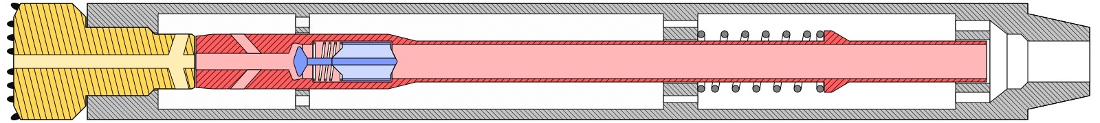
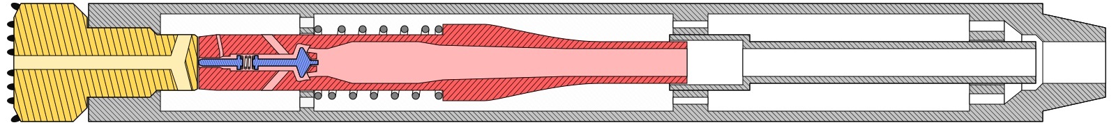
1989: Novatek Mud Hammer
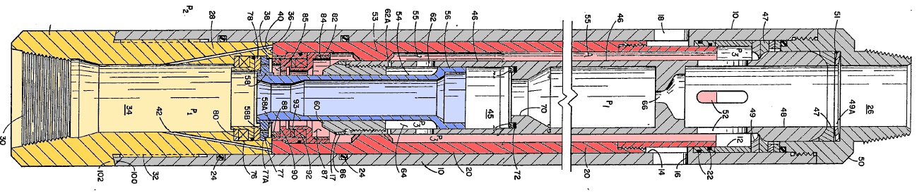
Novatek patented a new mud driven percussion dill in 1989 [30], placing the valve around the striking piston and using a hydraulic circuit parallel to the drilling mud flow. The percussion drive is driven by the hydraulic pressure difference between the inside and outside of the drill.
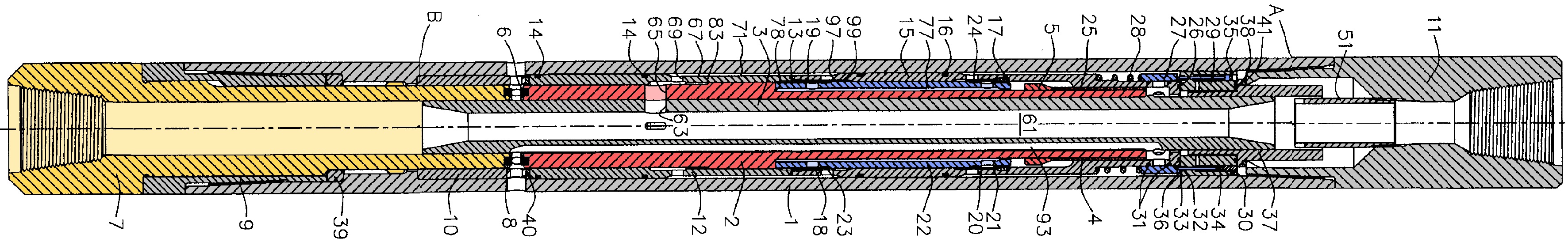
As the outer valve (22) is in its lower position the striking piston (83) will get pushed up: The backward surface is connected to the ring annulus through the inner channels (93) as the shutdown valve (27) is pushed downwards by the fluid flow. When reaching the upper position, the valve is pushed upwards by opening a channel (23), this changes the surfaces which pressure is applied to and moves the piston downwards.
The percussion drill was operated about 50 hours at drill tests in Germany. The valve lifetime was raised by using tungsten carbide and diamond coatings [31]. Until 2005, a fully integrated percussion jet assisted drill bit was developed [32].
1992: Cyphelly Ram Hammer
Ivan Cyphelly invented a new hydraulic ram hammer at Salzgitter Maschinenbau AG for the use at the German Continental Deep Drilling Programme (KTB) which makes explicit use of the hydraulic ram hammer effect [21]. The concept is kind of similar to the first hydraulic ram hammer drills but uses a moving momentum transfer tube connected to the hammer mass. Therefore no high pressure occurs at sleeve bearings [33].
A so called momentum valve inside the hammer is closing as the flow reaches a certain value. This interrupts the flow and the hydraulic inertia is transferred to the hammer mass, which is then hitting the anvil. The momentum transfer tube is then pushed back by a spring.
A further development of the cyphelly ram hammer used a fixed momentum transfer tube and a modified valve which allows a more continuous cycle. The hammer was also shortened as the first momentum tube had a length of about 10 m.
The Cyphelly ram hammer was subject to intense reasearch at the ITE of TU Clausthal. A simulation of the hydro-mechanical dynamics was programmed in a developed bondgraph model to analyze the motion sequence [34].
References
[1] H. S. Drinker, Tunneling, Explosive Compounds and Rock Drills. J. Wiley, 1878.
[2] “Inductee Database: Ingersoll, Simon,” National Mining Hall Of Fame and Museum. [Online]. Available: https://mininghalloffame.org/inductee/ingersoll. [Accessed: 17-Mar-2019].
[3] “Drilling Through History,” National Driller. [Online]. Available: https://www.nationaldriller.com/drilling-history. [Accessed: 17-Mar-2019].
[4] S. Ingersoll, “Improvement in Rock-Drills,” US112254, 28-Feb-1871.
[5] J. Ponce, The Technologies that Conquered Unconventional Reservoirs. ResearchGate, 2018.
[6] C. G. Cross, “Drills for Boring Artesian Wells,” US142992, 1873.
[7] G. Prikel, Tiefbohrgeräte. Springer Vienna, 1957.
[8] Л. Э. 0Граф and Д. И. Коган, Гидроударные машины к инструмент. Moskau: Недра, 1972.
[9] F. Heise, F. Herbst, and F. Heise, Lehrbuch der Bergbaukunde. Springer-Verlag, 2013.
[10] W. Wolski, “Deep-Boring Apparatus,” US699273, 1900.
[11] W. Wolski, “Tiefbohrapparat,” AT12595, 1902.
[12] H. Pennington, “Well Drilling Apparatus,” US1892517, 1927.
[13] J. A. Zublin, “Rotary Bit with Hammering Device,” 1861042, 28-Apr-1930.
[14] G. R. Samuel, “Percussion Drilling…Is It a Lost Technique? A Review.,” in Permian Basin Oil and Gas Recovery Conference, 1996, p. 7.
[15] R. Bassinger, “Percussion Drilling Tool,” US2645207, 1948.
[16] P. L. Guarin, H. E. Arnold, W. E. Harpst, and E. E. Davis, “Rotary Percussion Drilling,” Drilling and Production Practice, New York, p. 11, 1949.
[17] S. Grow, Roughnecks, Rock Bits And Rigs. University of Calgary Press, 2006.
[18] R. Bassinger, “Rotary Percussion Drilling, a review and a prediction,” The Oil and Gas Journal, pp. 111–112, 1950.
[19] P. L. Guarin and H. E. Arnold, “Rotary Percussion Drilling,” The Oil and Gas Journal, pp. 305–317, 1949.
[20] W. E. Harpst and E. E. Davis, “Experiments in Rotary Percussion Drilling,” The Oil and Gas Journal, pp. 182–187, 1949.
[21] R. Luy, “Untersuchung zur Wirksamkeit des Bohrprozesses beim drehschlagenden Bohren unter hohen hydrostatischen Drücken,” Dissertation, Fakultät für Bergbau, Hüttenwesen und Maschinenwesen der Technischen Universtität Clausthal, Clausthal-Zellerfeld, 1992.
[22] R. P. Vincent and L. B. Wilder, “Percussion Motor,” GB1245617, 1968.
[23] R. P. Vincent and L. B. Wilder, “Tool boosts drilling in hard formations,” The Oil and Gas Journal, vol. 67, no. 13, pp. 74–78, 1969.
[24] G. Klemm, “Tieflochhammer,” DE3343565A1, 1983.
[25] P. Gustafsson, “Hydraulic Down-The-Hole Rock Drill,” EP0394255B1, 1988.
[26] D. A. Bruce, R. Lyon, and S. Swartling, “The History of Down-The-Hole Drilling and the Use of Water-Powered Hammers,” p. 11, 2013.
[27] P. Gustafsson, “A Hydraulic Impact Motor,” EP0733153B1, 1994.
[28] J. Riechers and V. Bracke Rolf; Wittig, “Innovatives hydraulisches Bohrverfahren für die oberflächennahe Geothermie als Alternative zum pneumatischen Bohrstandard,” Bachelor-Thesis, Hochschule Bochum, Bochum, 2010.
[29] V. Hartung, V. Wittig, and R. Bracke, “Design and test of hydraulic DTH mud hammers to improve service life, ROP, borehole cleaning and control for deep, hard rock geothermal drilling,” in Proceedings, 2016.
[30] K. Maeggi and R. Bracke, “Energiebilanz beim Einsatz von wasserbetriebenen Imlochhämmern bei mitteltiefen Geothermiebohrungen,” Master-Thesis, Hochschule Bochum, Bochum, 2013.
[31] D. R. Hall, D. S. Pixton, and Y. Xiang-Guang, “Down-hole Mud Actuated Hammer,” US5396965, 1989.
[32] D. S. Pixton and D. R. Hall, “A New-Generation Mud-Hammer Drilling Tool Annual Report,” Provo, UT, p. 18, 05-Aug-1997.
[33] J . V. Fernandez and D. S. Pixton, “Integrated drilling system using mud actuated down hole hammer as primary engine,” p. 35, 2005.
[34] I. J. Cyphelly, “Einrichtung mit einem für Erdbohrzwecke vorgesehenen hydraulischen Hubgenerator,” EP0303635B1, 1988.
[35] F. Nickel, I. Cyphelly, and J. Thoma, “KTB-Bohrhammerentwicklung Projektphase II a,” 1993.
Thank you for a very good history of the DTH hammer. I was trying to find info on the Wolsky hammer that I read about many years ago.
Great information about fluid hammers, kudos!!