
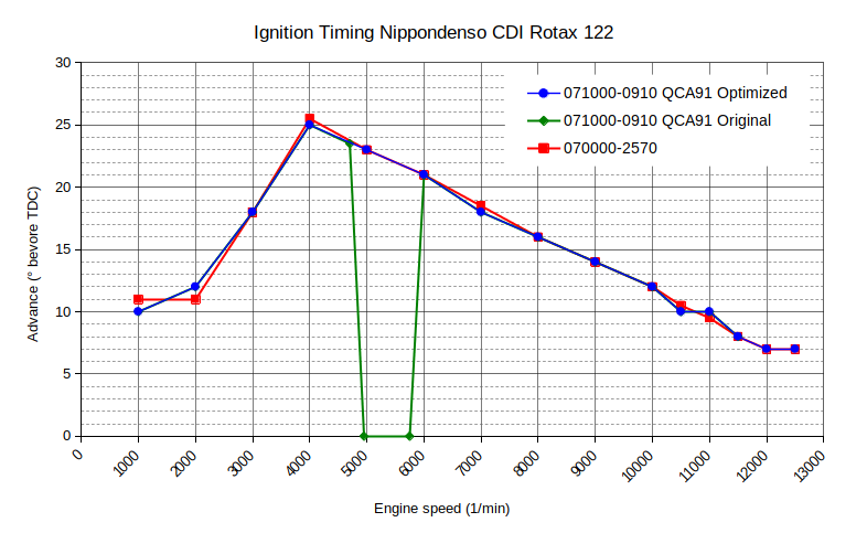
The “power hole” of the control unit 071000-0910 QCA91 can be removed by cutting a dedicated circuit board part on the back of the control unit.
Between 4,800 rpm and 6,000 rpm, the ignition advance of the “unrestricted” control unit is set to a value of 0°. This results in a power loss of about 40 %. It serves to comply with the emission limit values that were in effect at that time.
Please note: This modification will result in an expiration of the according homologation.
This modification is not possible with Nippondenso 070000-2570 CDI (The difference can be seen in the article Ingition Systems (CDIs) with some pictures).
The circuit to cut out is centered at the bottom of the back side in a height of about 3 to 4 mm.
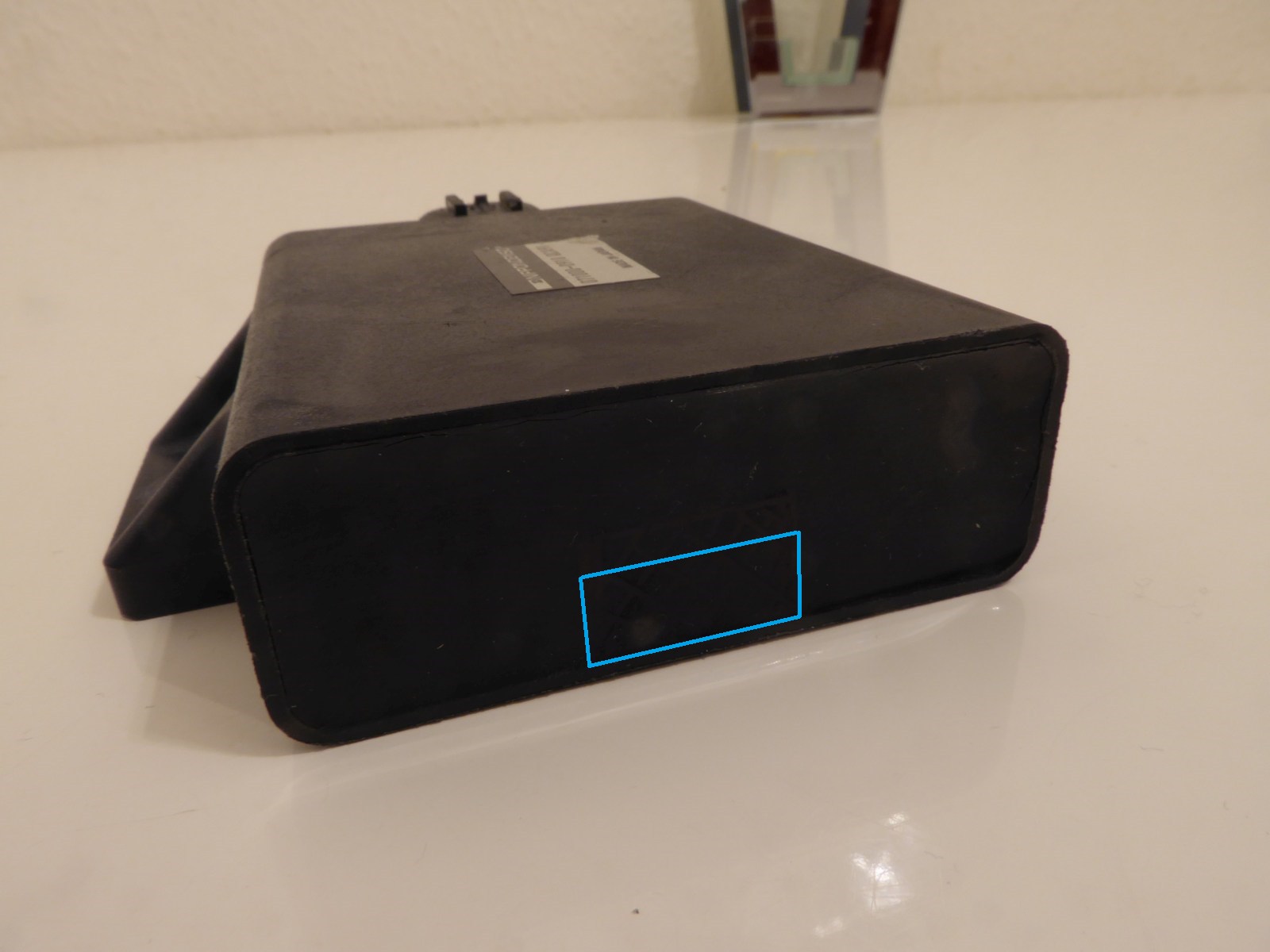
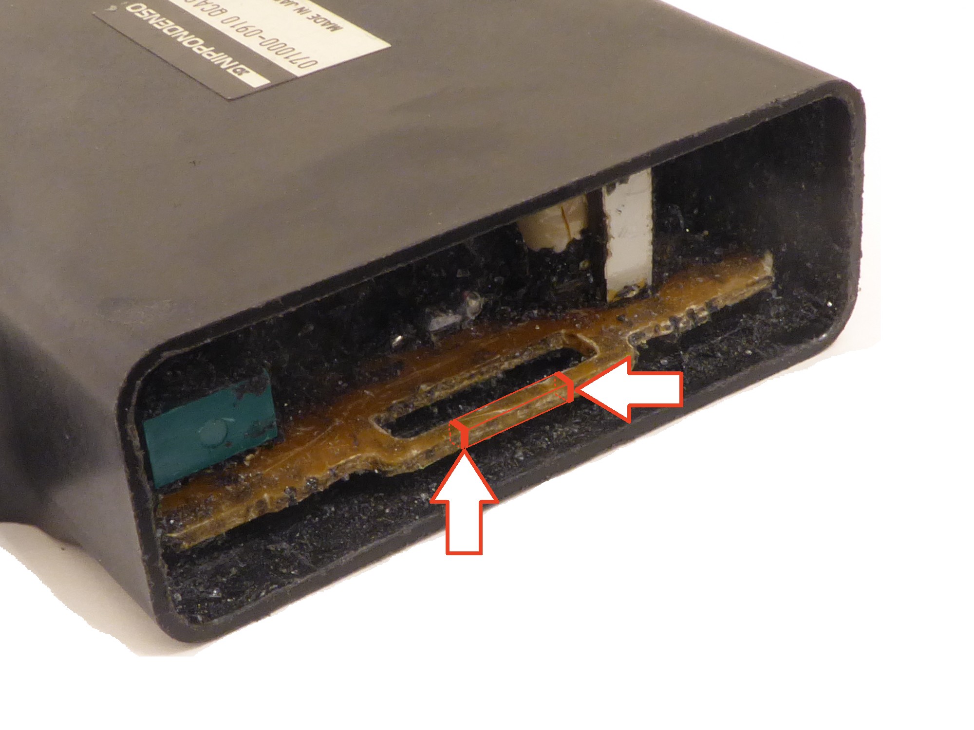
At this point the board has a conductor track that has been led out for this purpose, there are no other components in the vicinity so that nothing can be cut through by mistake. This can be seen on the following pictures:

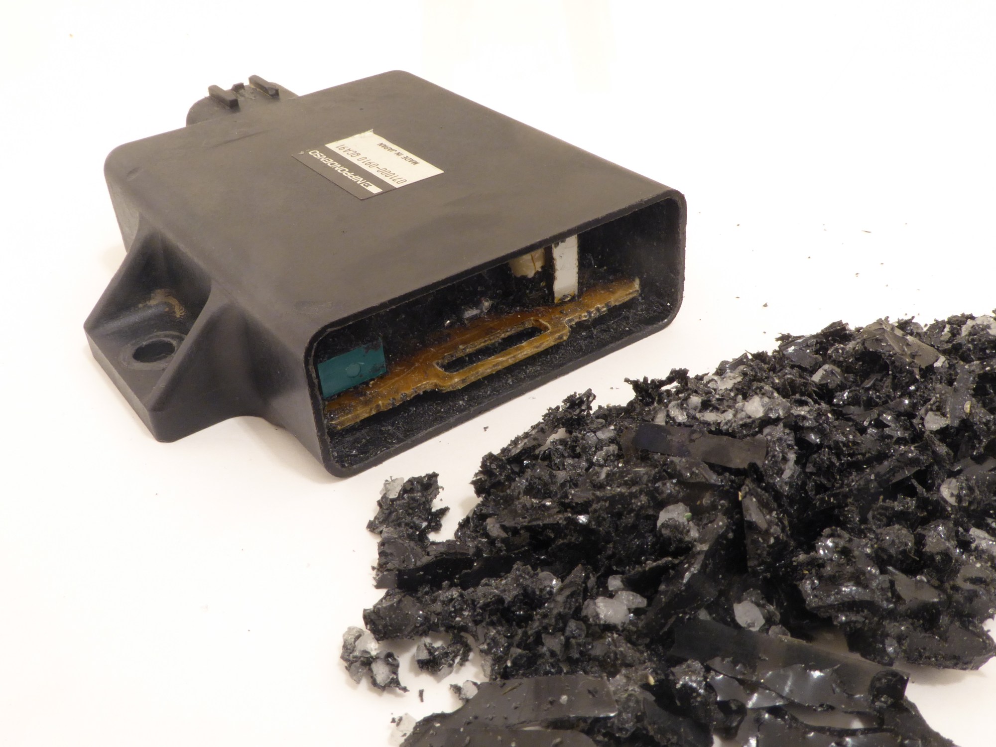
Removed potting compound 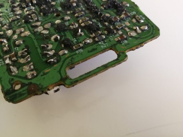
Conductor track (bottom) 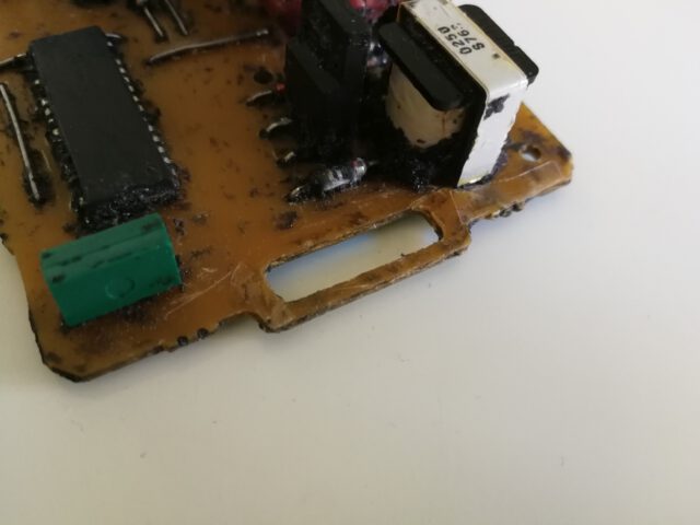
PCB (top)


To remove the power gap, cut the piece of the protruding pcb at the rear. The potting compound can be easily cut out with a knife or a screwdriver, it is not very resistant at the back of the CDI.
The conductor path, which then appears, is then cut out with a small electronics side cutter.
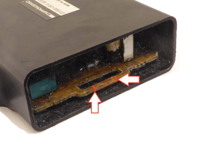
Cut and remove this part of the PCB 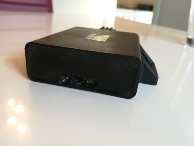
Removed conductor track (less potting compound removed)

With some skill it is also possible to remove further potting compound and solder a small switch on the remaining pcb tracks and glue it to the casing. On the pictures above you can see that there are no components in the way when placing the switch slightly to the left. If you dig deeper through the potting compound, it also consists of glass granules.
The cut out area is closed again with black silicone or a similar material, then the modification is finished.