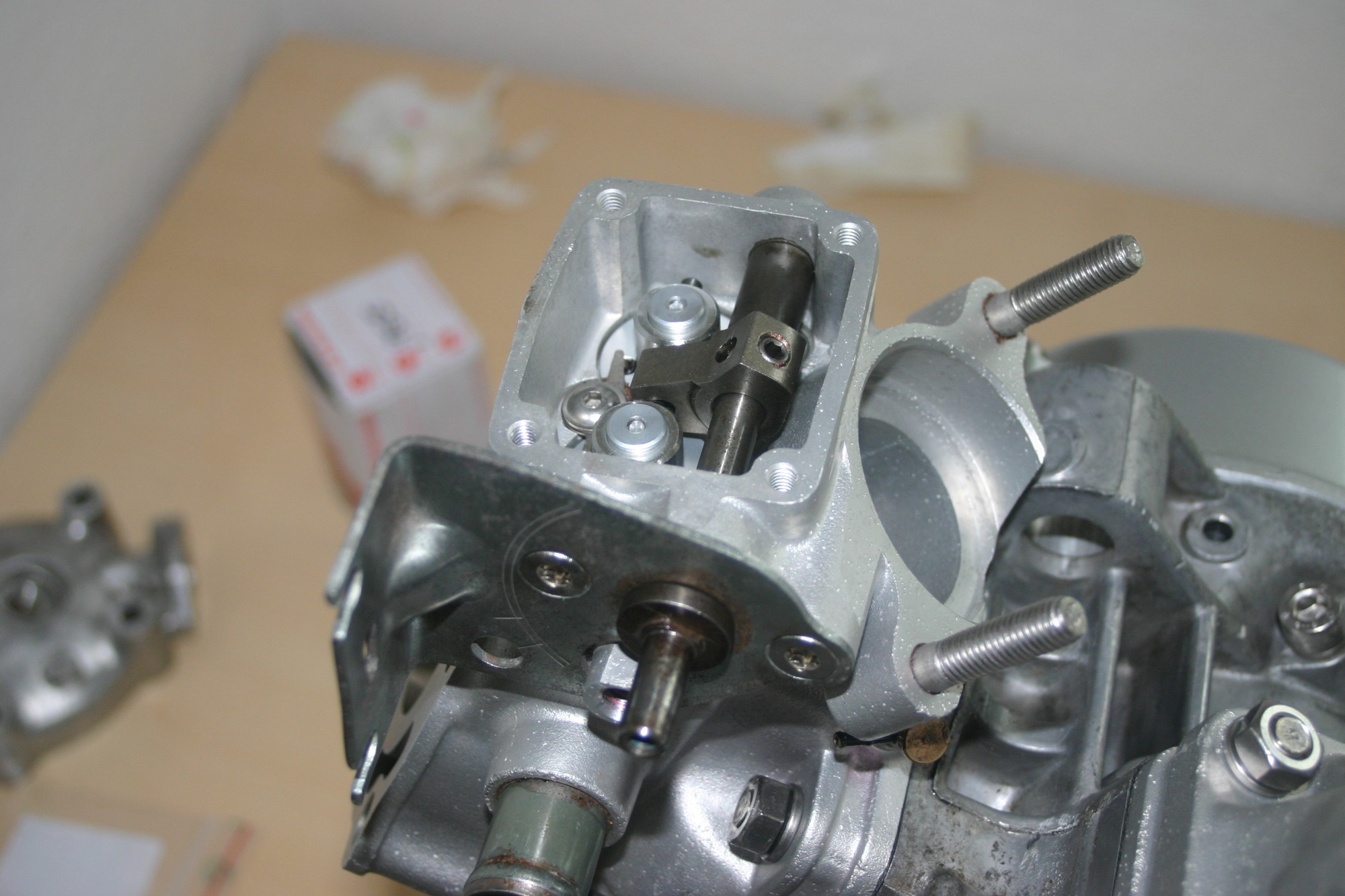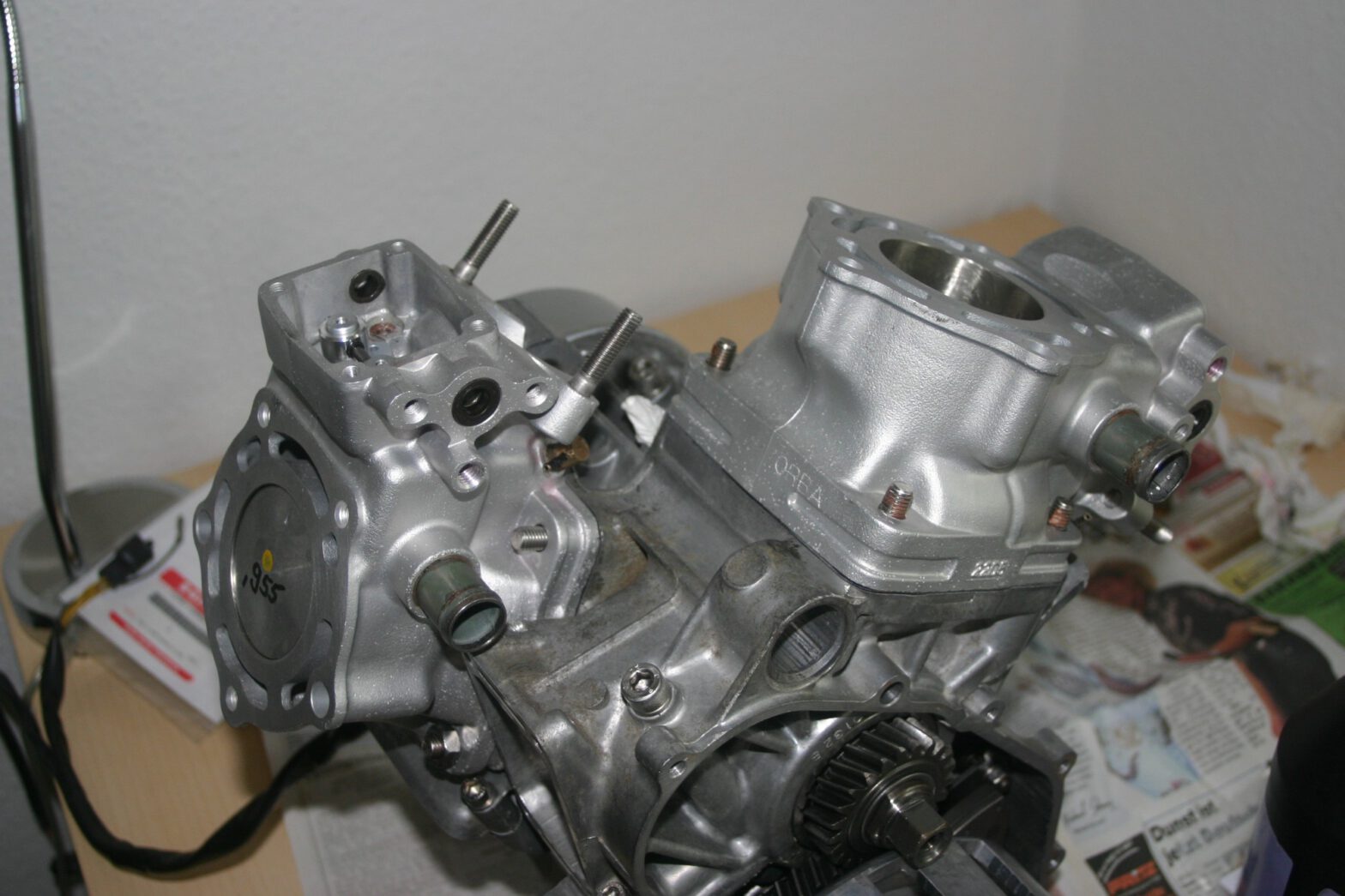
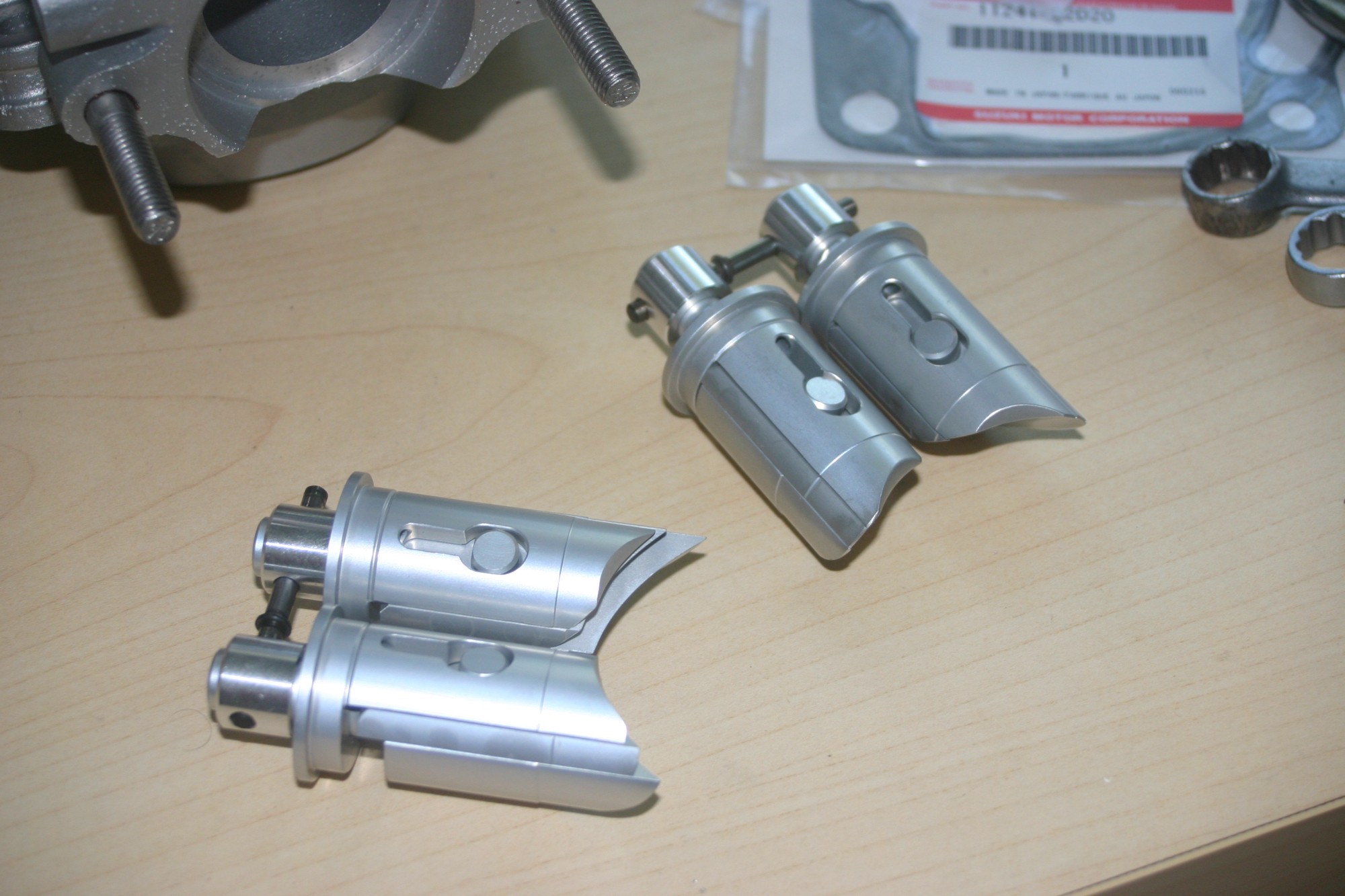
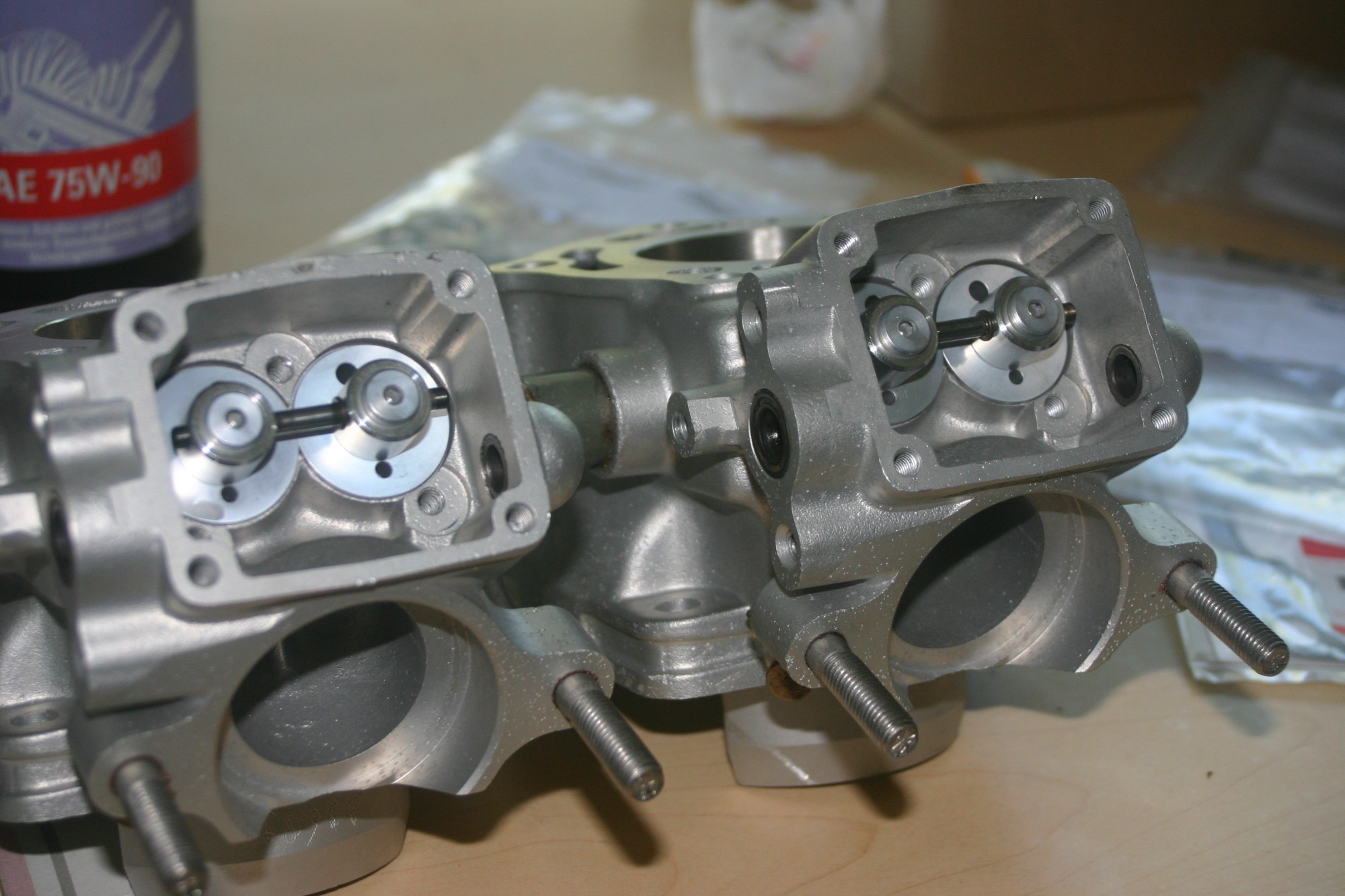
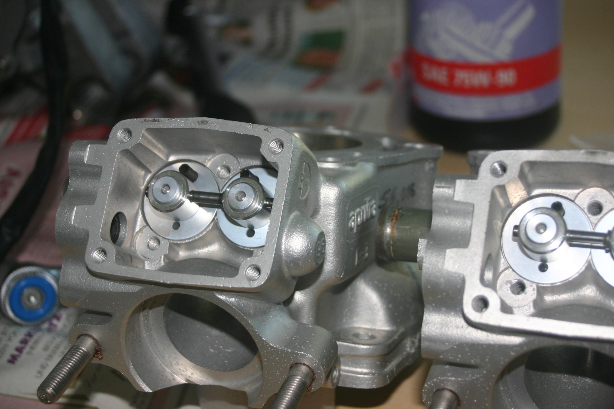
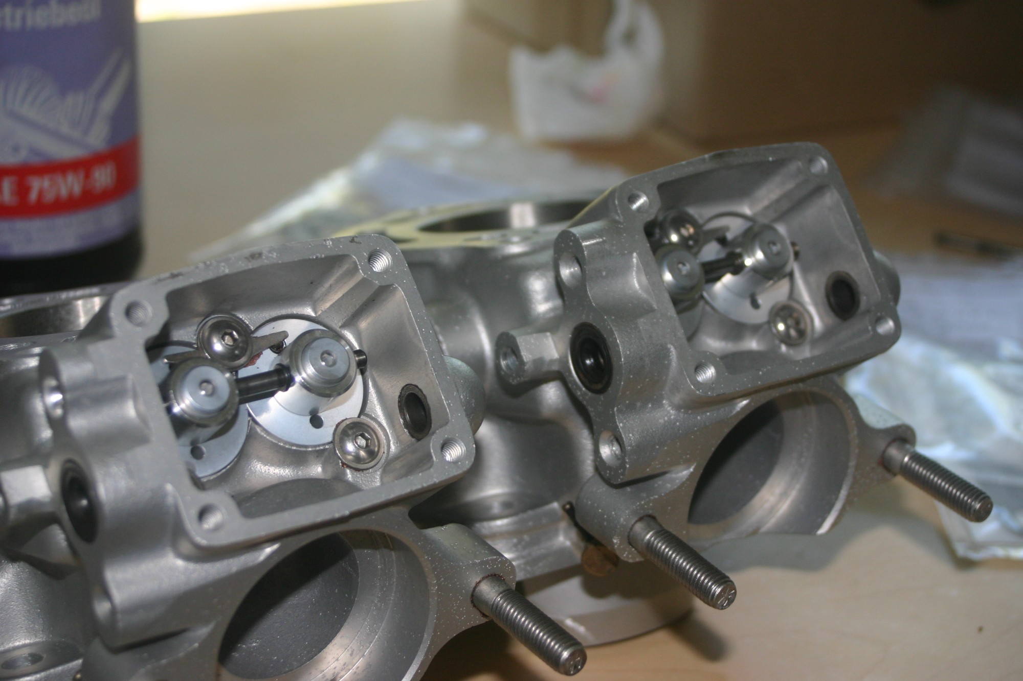
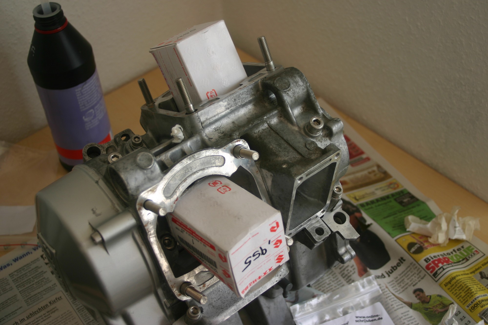
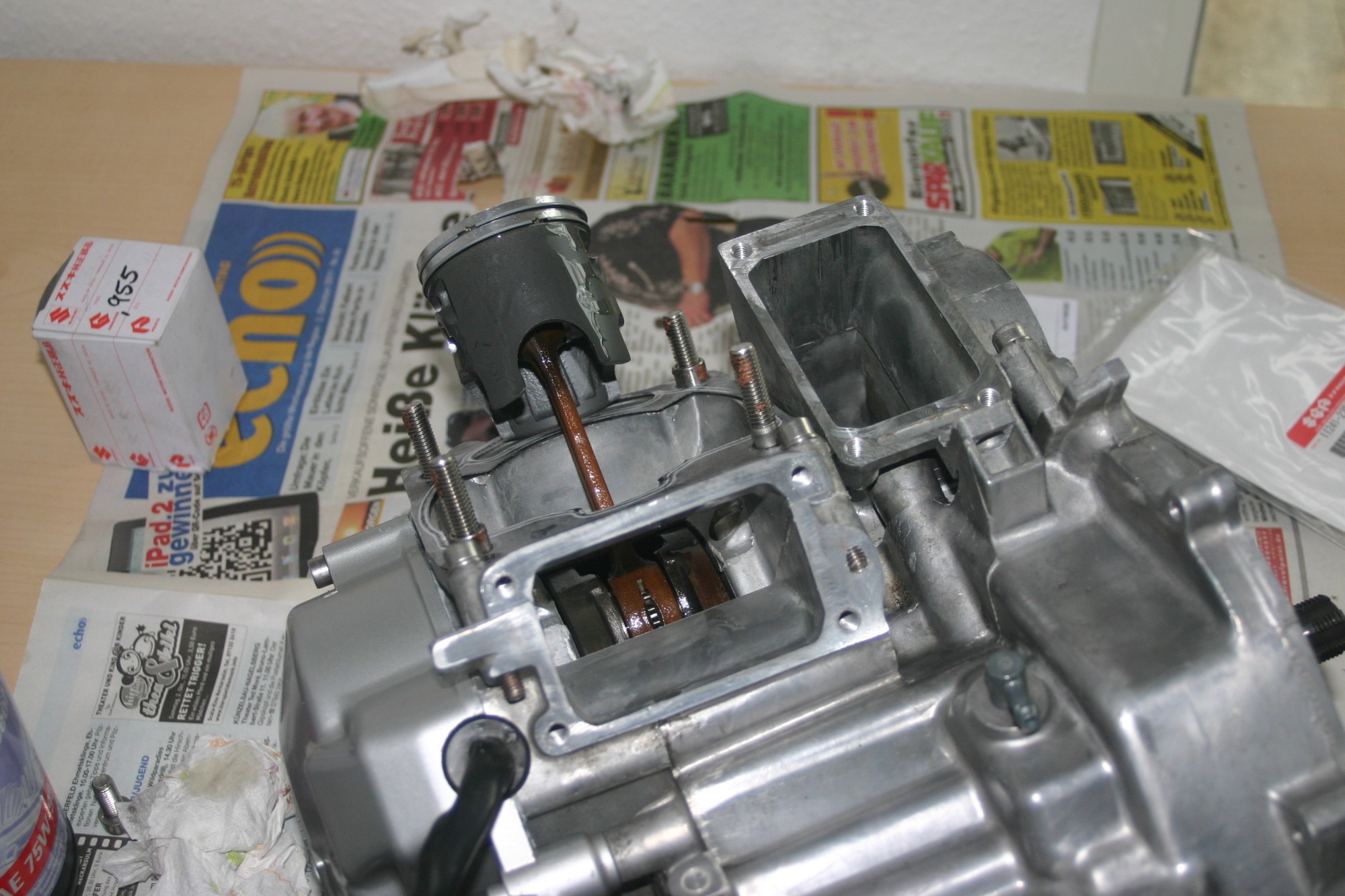
The exhaust power valves were installed before the cylinders were mounted. For the exhaust, a new threaded bolt M8x30 was screwed in.
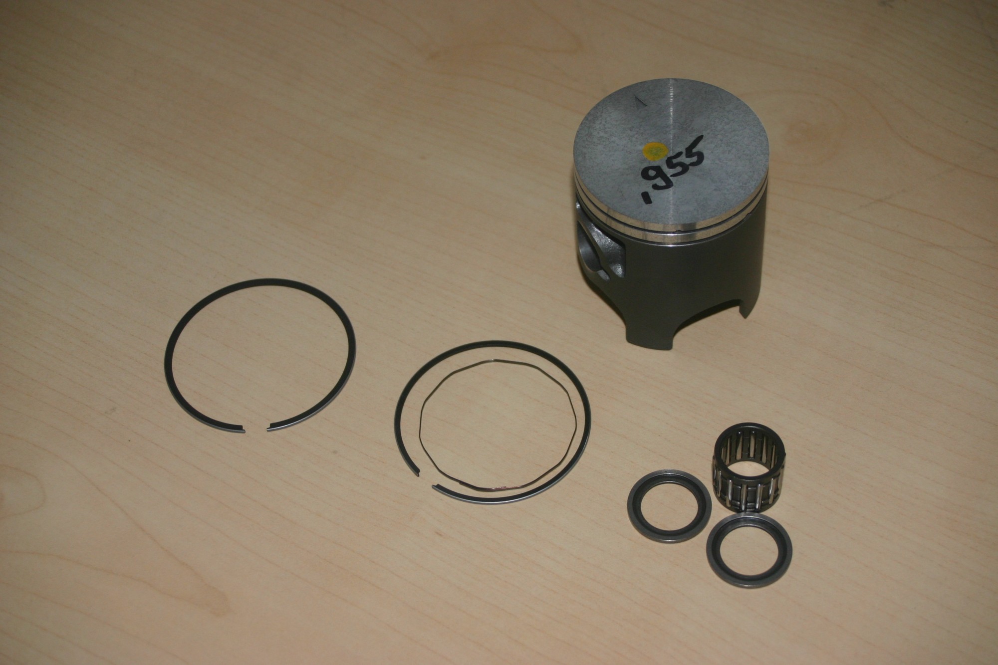
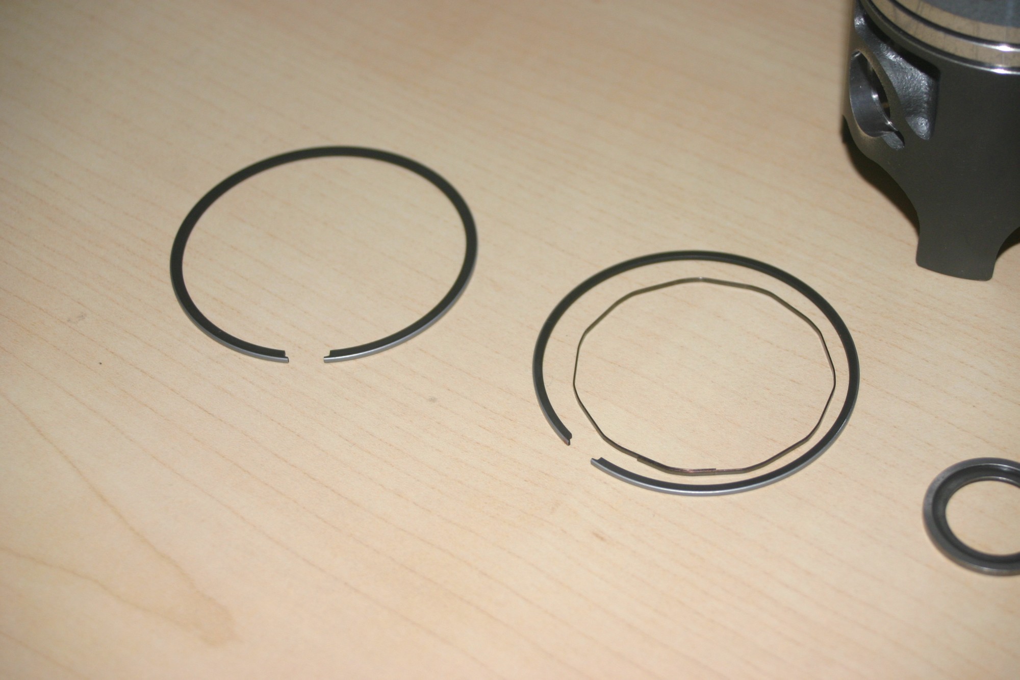
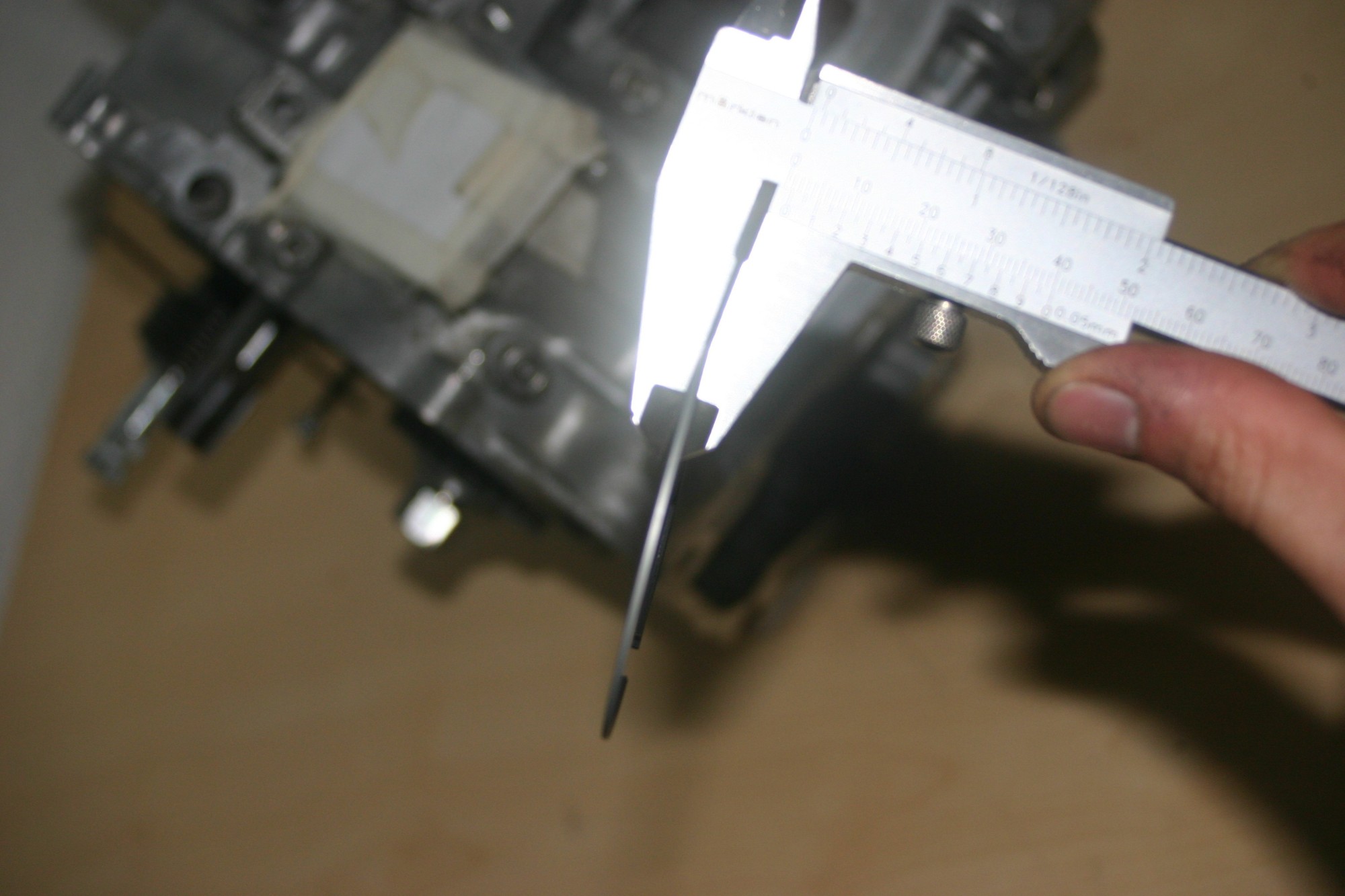
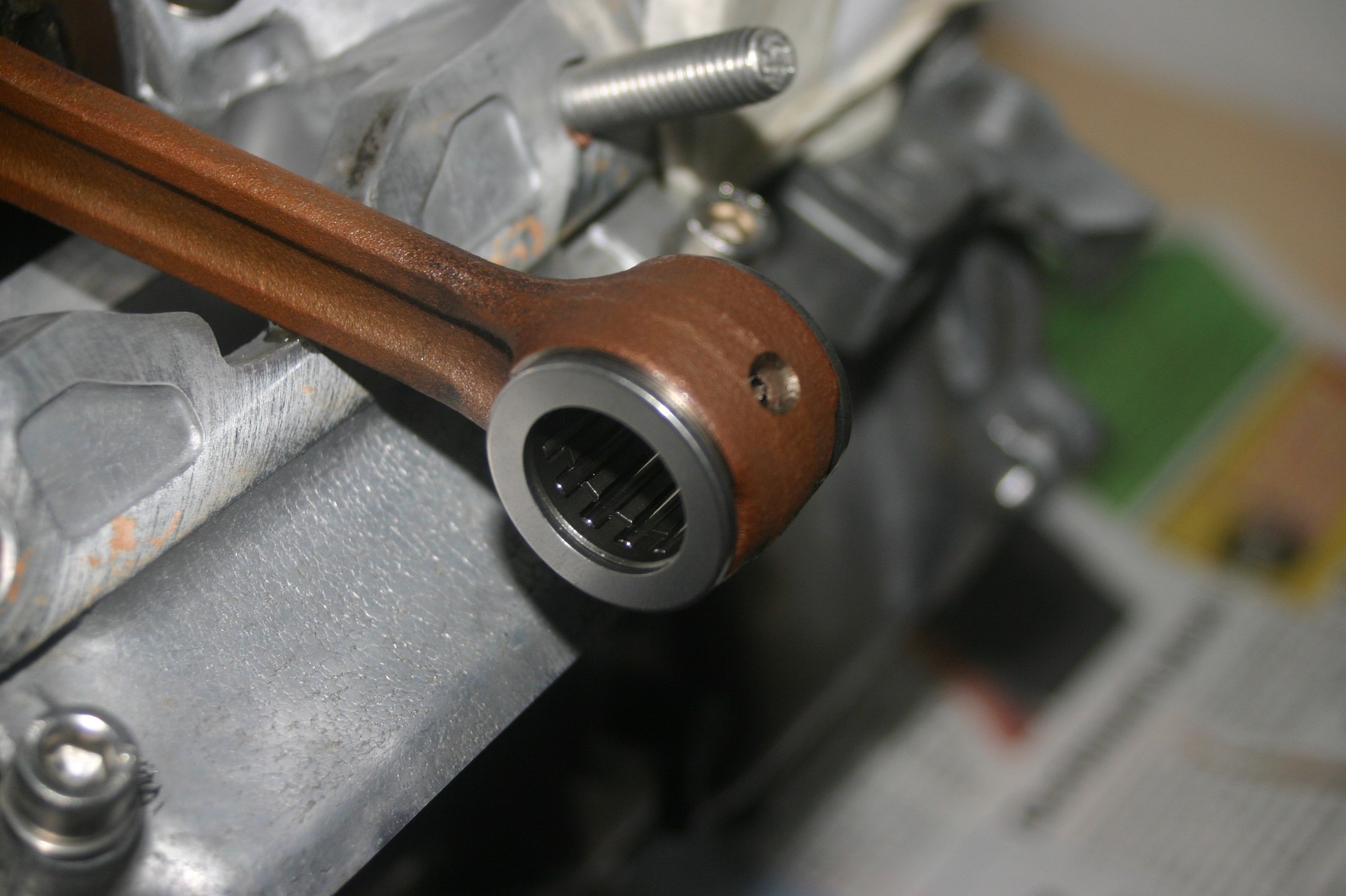
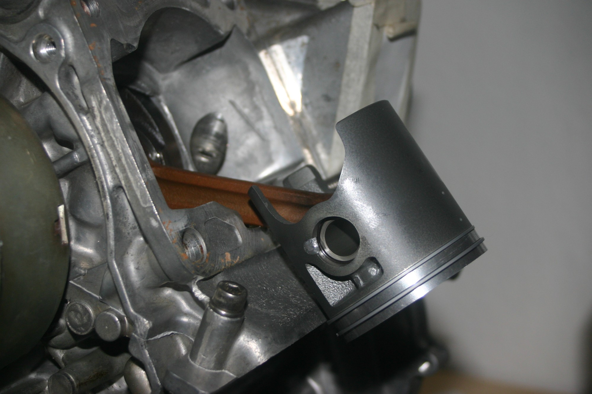
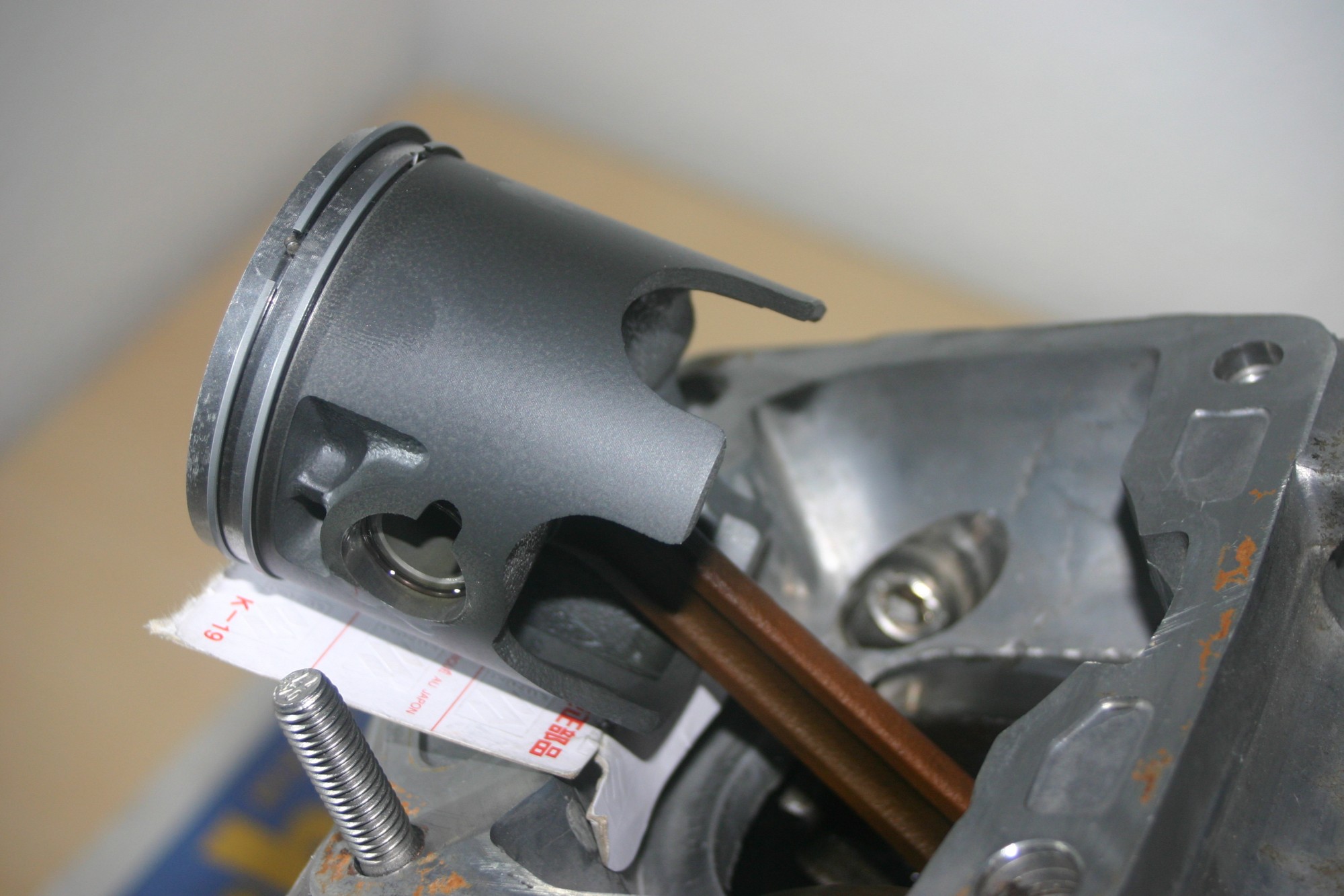
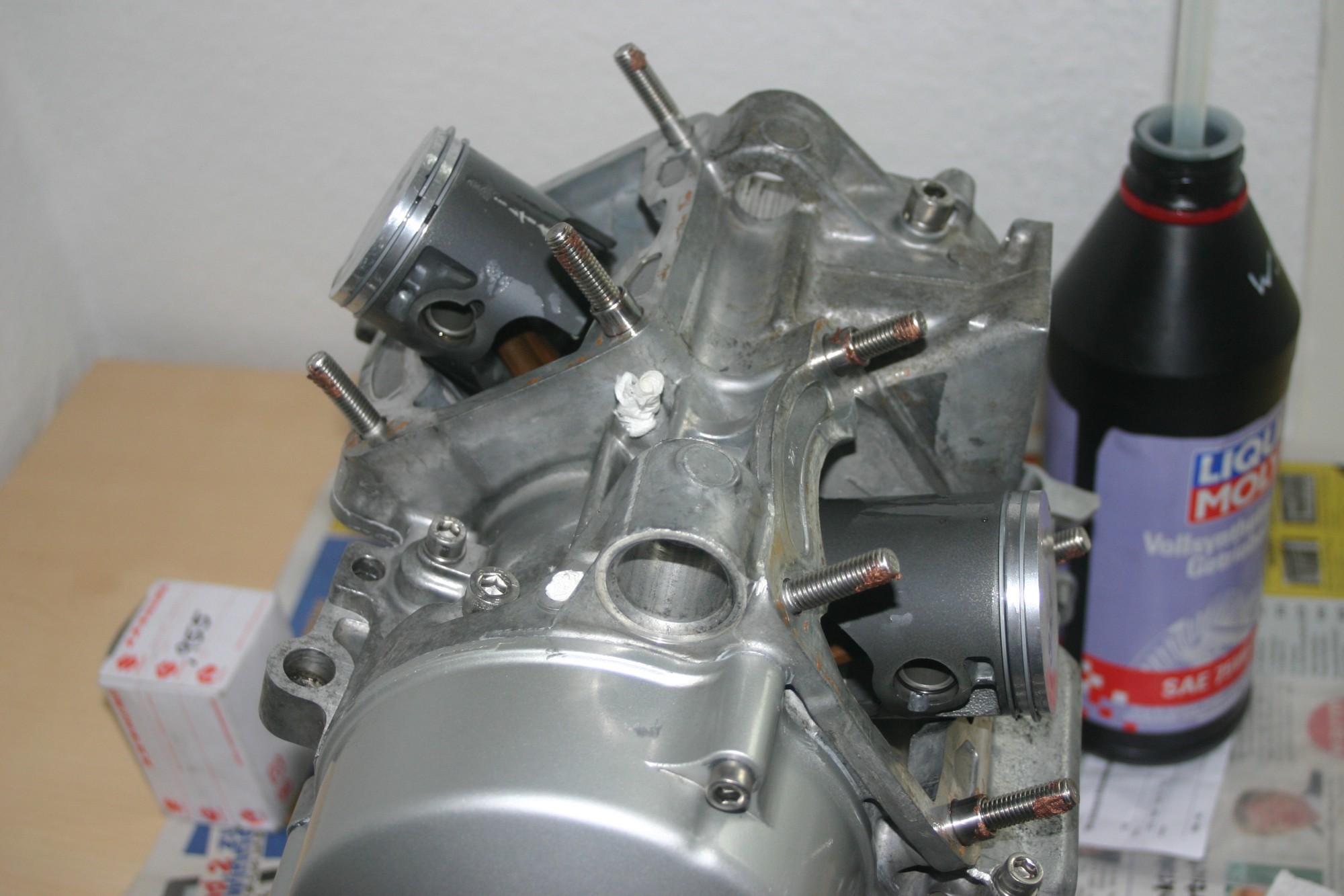
This was followed by the assembly of the pistons. For this the bearings are oiled and inserted with the friction discs into the eyes of the connecting rod. The piston kit includes two different rings and a kind of spring washer. The thicker ring must be inserted with the chamfered side up into the upper groove, this is also marked with a nearly invisible letter. You can also use a caliper gauge to find out which of the sides is chamfered, because the ring can then be tilted between the measuring legs as shown in the picture. The spring ring and the thin ring are placed in the lower groove of the piston.
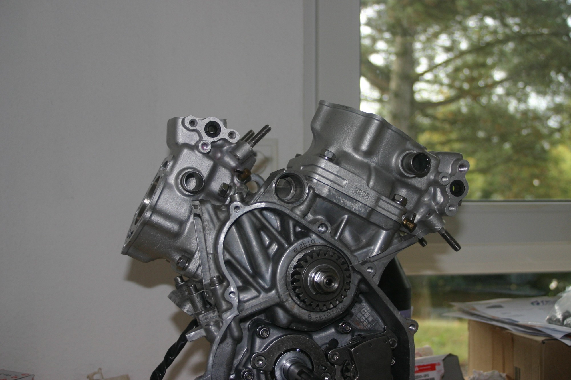
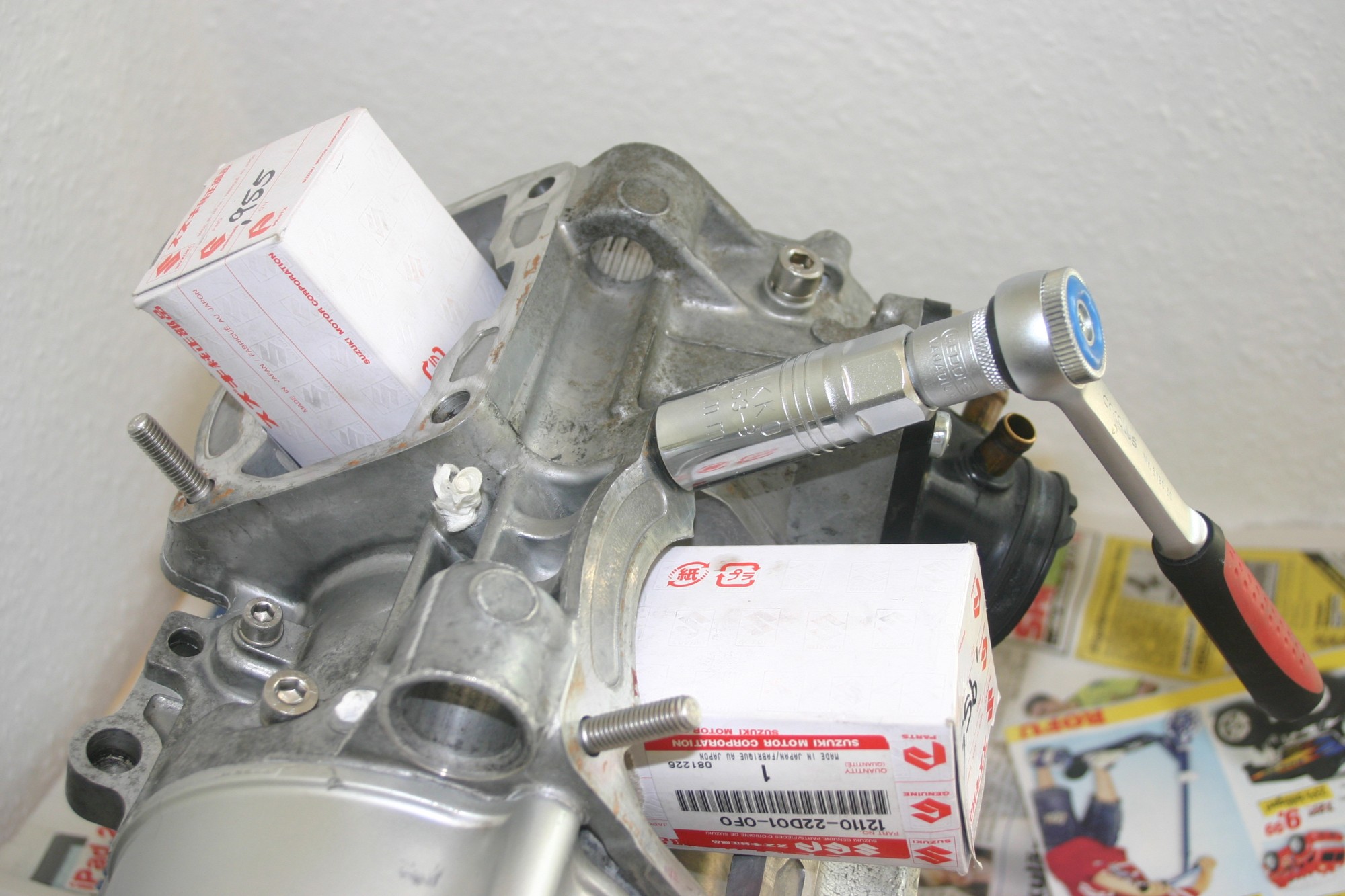
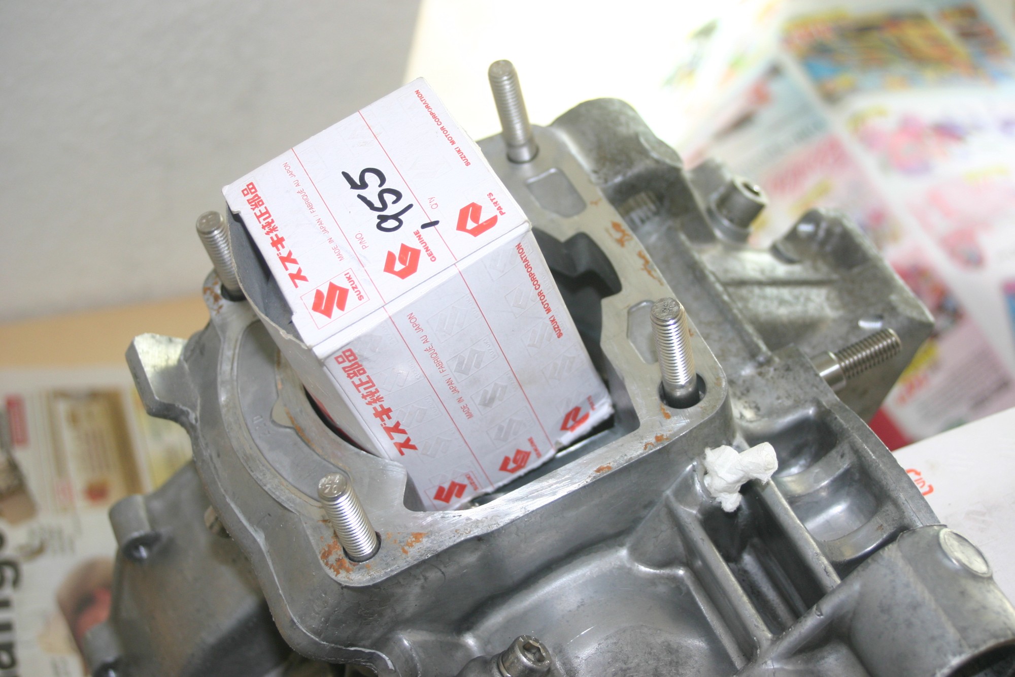
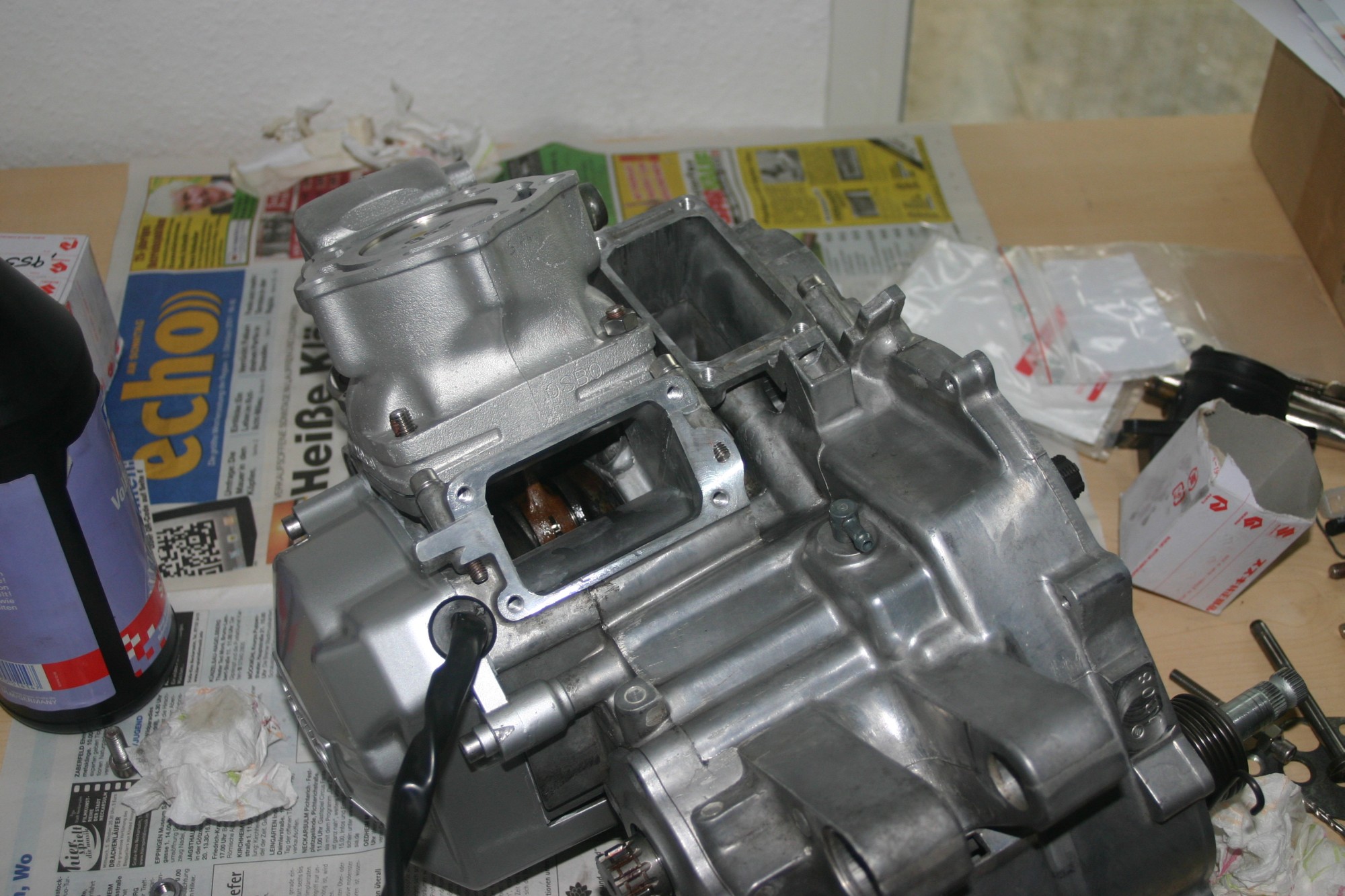
The cylinders are mounted on stud bolts, which are mounted with a stud bolt extraction tool. Threaded bolts with different lengths are used here, 30 mm, 2x 35 mm and 40 mm. As always I lubricate them with anti-seize paste, but the workshop manual recommends a screw lock. The nuts should be tightened with 23 – 27 Nm, but you can only use special torque wrenches with insertable forks – I don’t have such a tool. Here I clamp the torque wrench in a vice and grip it with the lever length of the suitable wrench. This way I get a rough feeling in my wrist how much I have to tighten the nuts with the wrench.

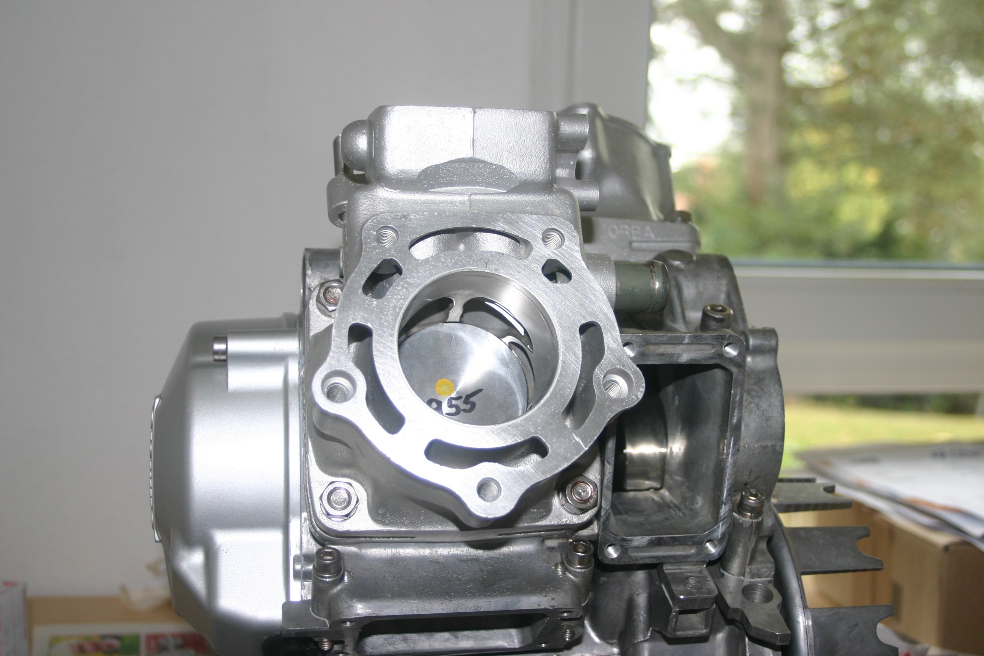
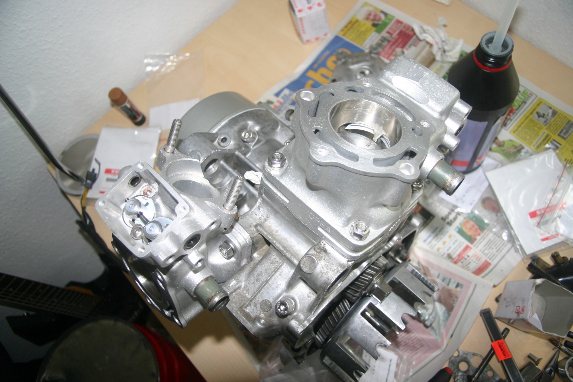
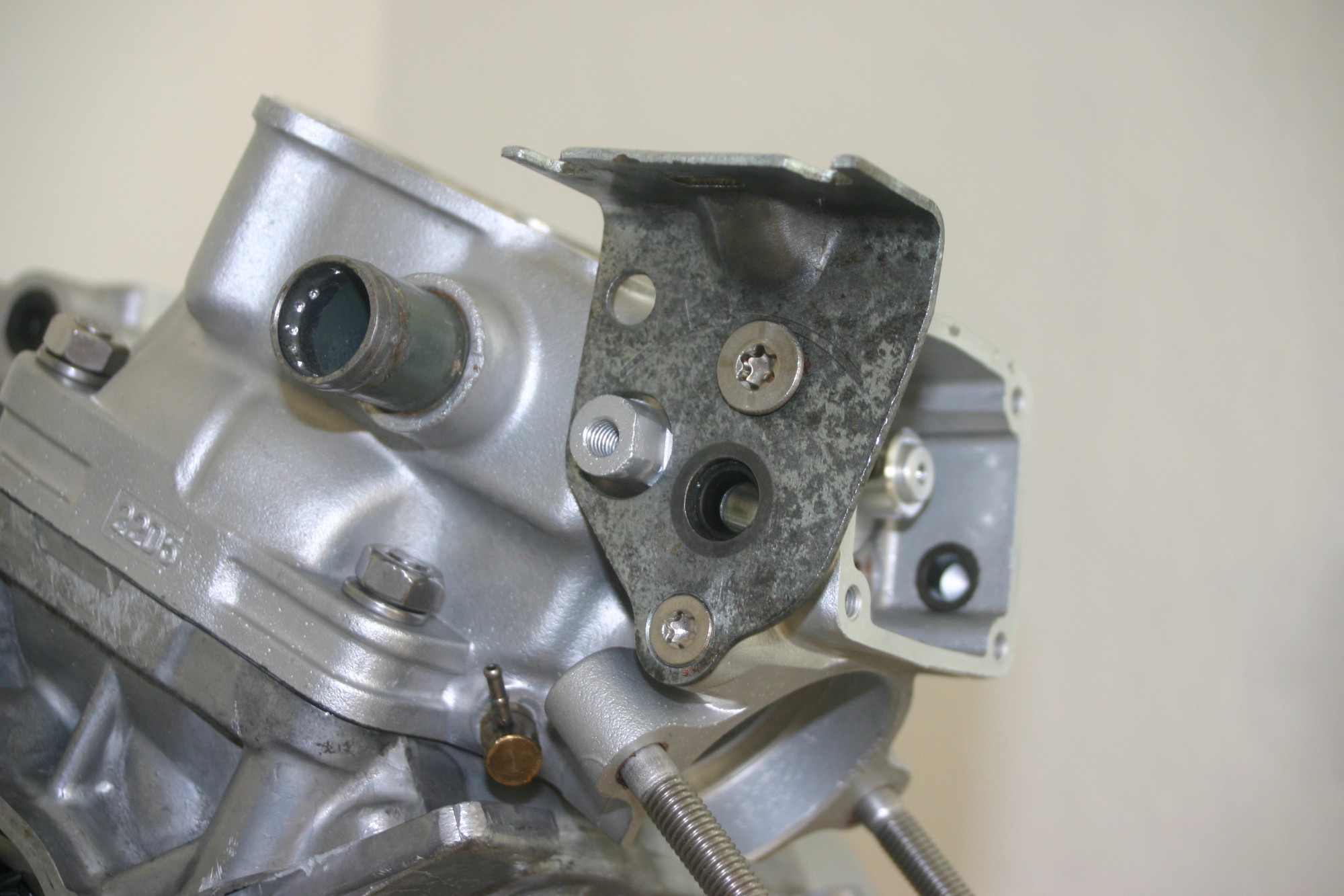
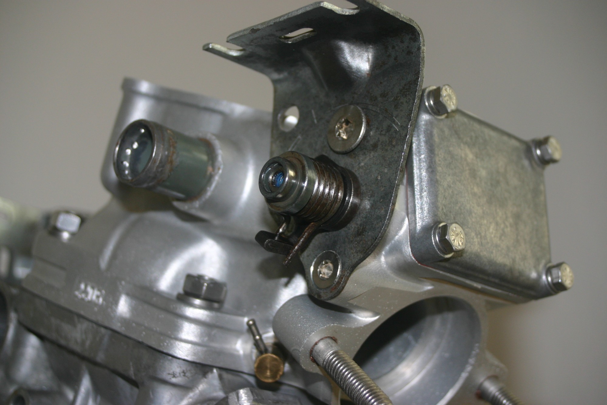
Now another part of the outlet slide mechanism is mounted. Here I had to drill out damaged screws on both cylinders and replace the threads with a M8 thread – this is the main reason I always use anti-seize and no screw lock. As with the gearbox, Torx screws are used here, because loosening these hexagon socket screws was already a pain.