The YouTube algorithm suggested a video from user argilaga about a power plant simulator for the RBMK reactors some time ago. I have now also dealt with this simulator myself and would like to share my experiences in this blog entry. Since I have already dealt intensively with the start-up of a coal-fired power plant, I would like to try to apply my experience to the RBMK reactor and pass it on.
In the meantime, I have also started my own simulation project which you also might want to check out.
The company “Simgenics” offers a free RBMK simulator download on its website. Originally the simulator was sold on CD as “CHERNOBYL, The Legacy Continues” for Windows 3.11 and Windows 95. This had the charm of video games of the time, there were short, real recorded videos with real people as cutscenes and you basically had the task of keeping the power plant running despite its malfunctions.
The new version by Simgenics, which now also runs under Windows 10, works without incidents and (unfortunately) without the nice cutscenes. Also loading and saving of game states is no longer possible, there is only a fixed initial state when starting the simulator. Also the functions for the economy of the plant have been removed. Nevertheless, the simulation of the control loops and the power plant control is very practical and accordingly complex, even without malfunctions. You won’t come far without technical and background knowledge, just like in reality.
Nevertheless, there are a few details about the simulator that are not completely unimportant and that help to understand why things are the way they are.
Simulator Model
The simulator replicates the plant in a simplified way in many parts and has 25 fuel elements and 25 control rods arranged in a 5×5 matrix. The second circuit flows through every second fuel element, not the left or right side. Some valves on some systems must and can be controlled individually, some systems are fully automatic and can start up with just one mouse click.
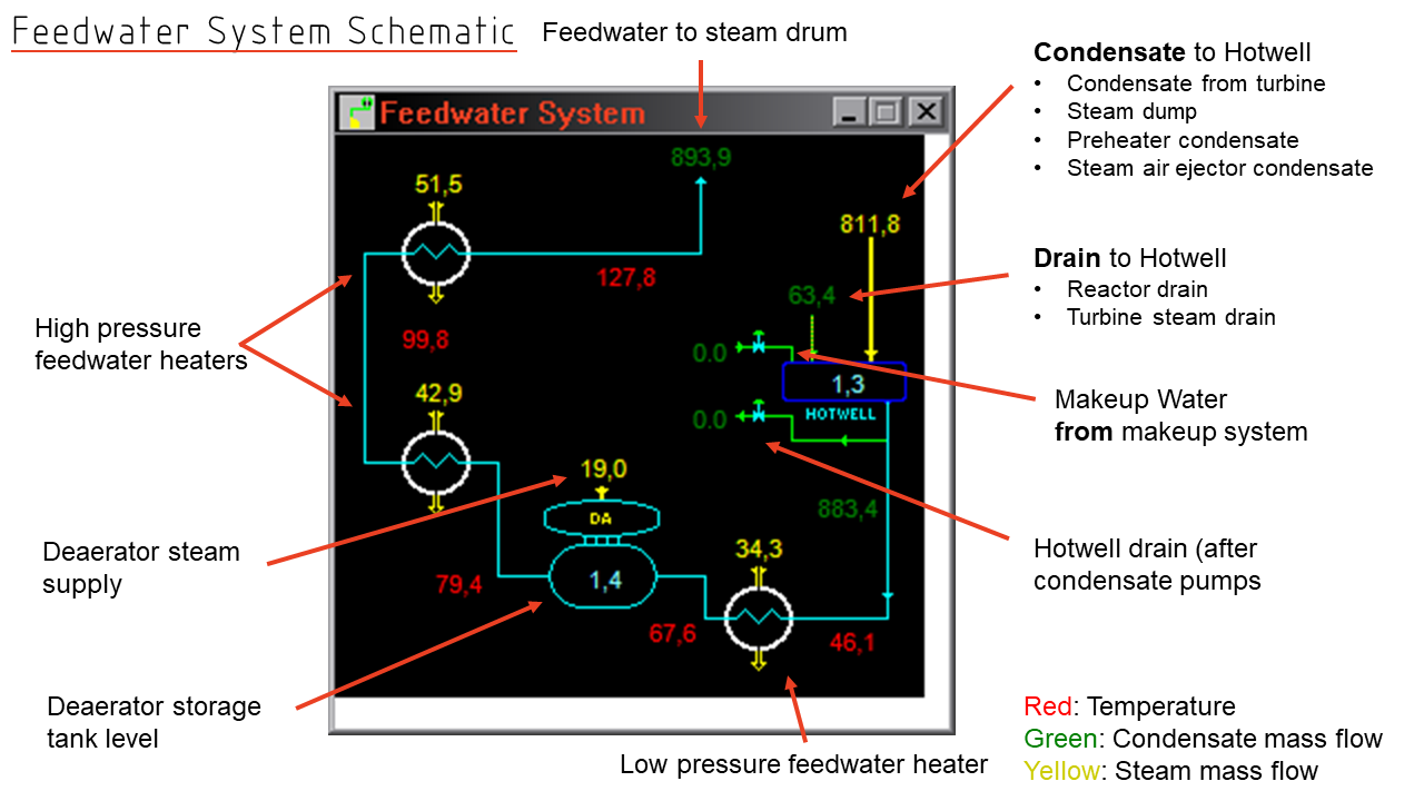
The following picture is based on the overview picture of the simulator and shows almost all plant components.
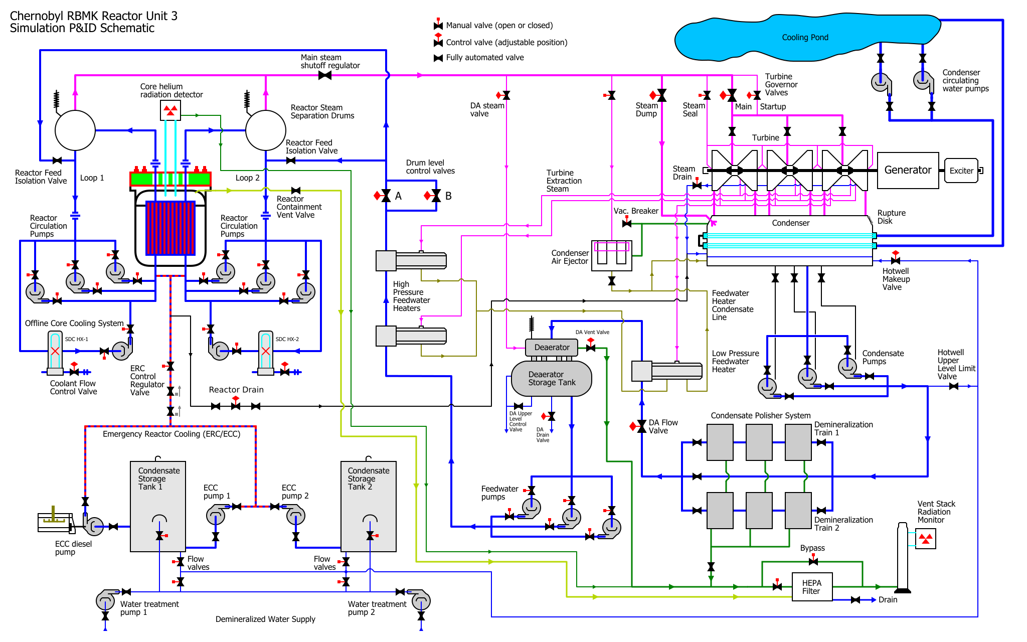
In this schematic I intentionally replicated the simulator’s symbols and did not use standardized symbols to stay close to the original. The schematic is also available as PDF and without labels (PNG, PDF).
Initial and Starting Conditions
The simulator always starts with initial conditions that describe the state of the power plant. These initial conditions are stored in an .ICD file, for “Initial Conditions”. The file chernobyl04.ICD which is located in directory \CHRNOBYL\FILES\IC_DATA is the file containing the initial conditions on simulator start. If yoi copy the file ICSELECT.EXE into the main directory, it can be run and the assignment of the other ICD files can be seen, which are still in this directory:
- chernobyl01.ICD: Plant Operator. Hardly any incidents, power plant at full load (Easy).
- chernobyl02.ICD: Shift Supervisor. Incidents, only 80% load, power plant barely breaking even (More difficult).
- chernobyl03.ICD: Chief Engineer. Serious trouble, only 50 % load, the power plant makes financial losses and the output must be increased (Very Difficult).
- chernobyl04.ICD: Plant Manager. Lots of damage, power plant off the grid, significant economic losses and strained personnel (Most difficult).
You can load the other files by replacing the file chernobyl04.ICD with other ICD files. Unfortunately, the state chernobyl01.ICD cannot be loaded, because the simulator in the current version is terminated immediately with core meltdown at 100% neutron flux in the reactor. Other initial conditions can be found in the folder CHRNOBYL\FILES\SAVED, these can be used as well.
The first problem at this point is: The power plant cannot be started in the original state as a power plant manager, because the rupture disk at the condenser is cracked and this must be repaired first, but the repair menu is not included in the new simulator version. There are so called ICD fixes in the web, where the rupture disc was repaired. Another problem is the xenon poisoning. When starting as a power plant manager, the xenon level increases continuously.
Simulator Operation
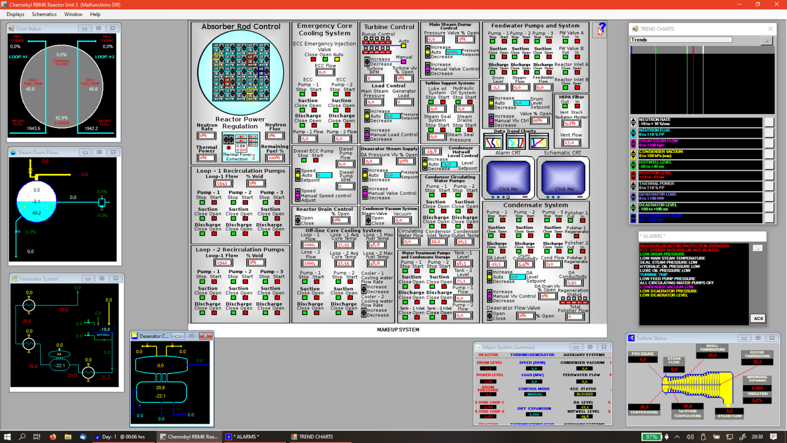
The simulator starts with a kind of replica of a small console, here a few important measured values are also displayed directly. The red and green buttons are only decorative and cannot be operated. If you click on a system area, a window opens for the operation of these system parts. With a right click on the console all windows are brought into the background or the foreground.

At ” Schematics” several schematics of individual plant areas can be displayed in addition to an overview schematic, which can be displayed e.g. next to the control panel. You can also move the control panel by moving one of the open windows to the edge of the main window and using the scroll bars, but this is reset when the window size is changed.
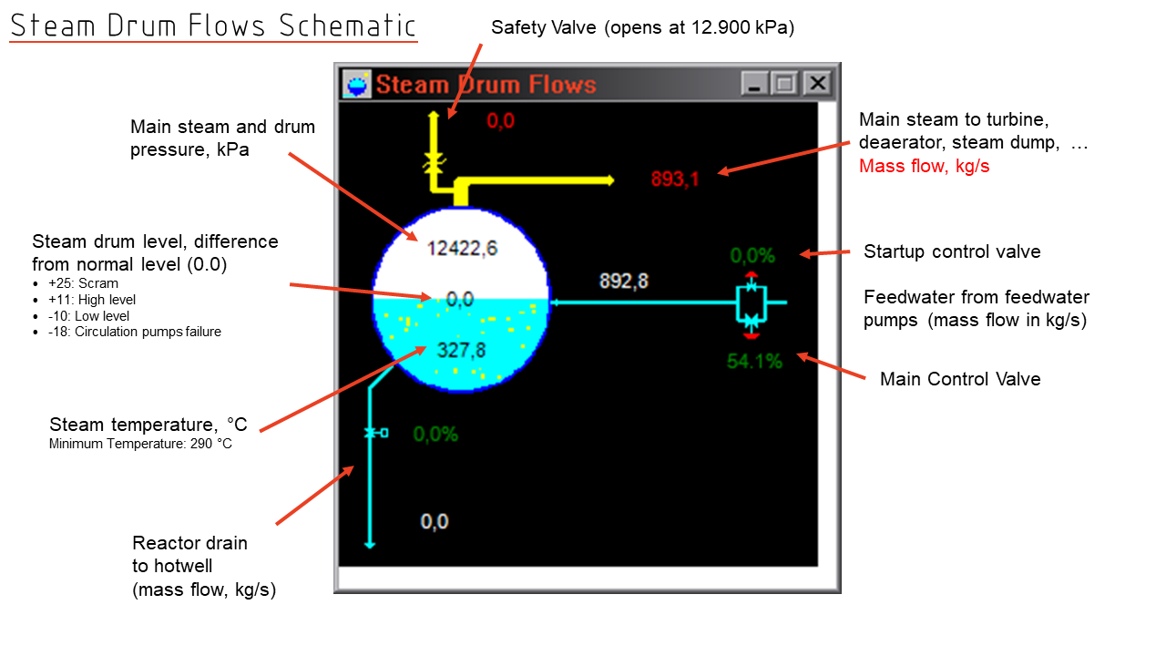
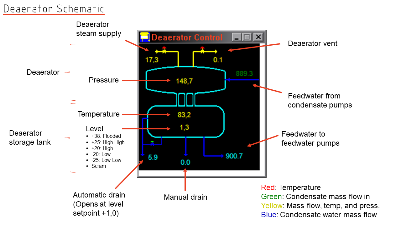
The values on the schematics are explained a bit on the following pictures.
The variables shown on the trend displays can be assigned as desired by selecting a measurement from the drop-down menu under “Trends” and then clicking on the button to the right of the color.
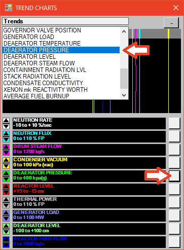
With the arrow keys on the left side the trend can be shifted to the left or right (e.g. if lines are too close together).
Controlling the Reactor
The reactor is controlled by the two windows “Reactor Power Regulation” and “Absorber Rod Control”.
The control rods of the reactor can be moved manually by pressing “Pull Rods”, “Insert Rods” and “Hold”. With “Center Core Only” only the control rods in the inner core are moved (for start-up). The speed can be set by selecting s, m or f.
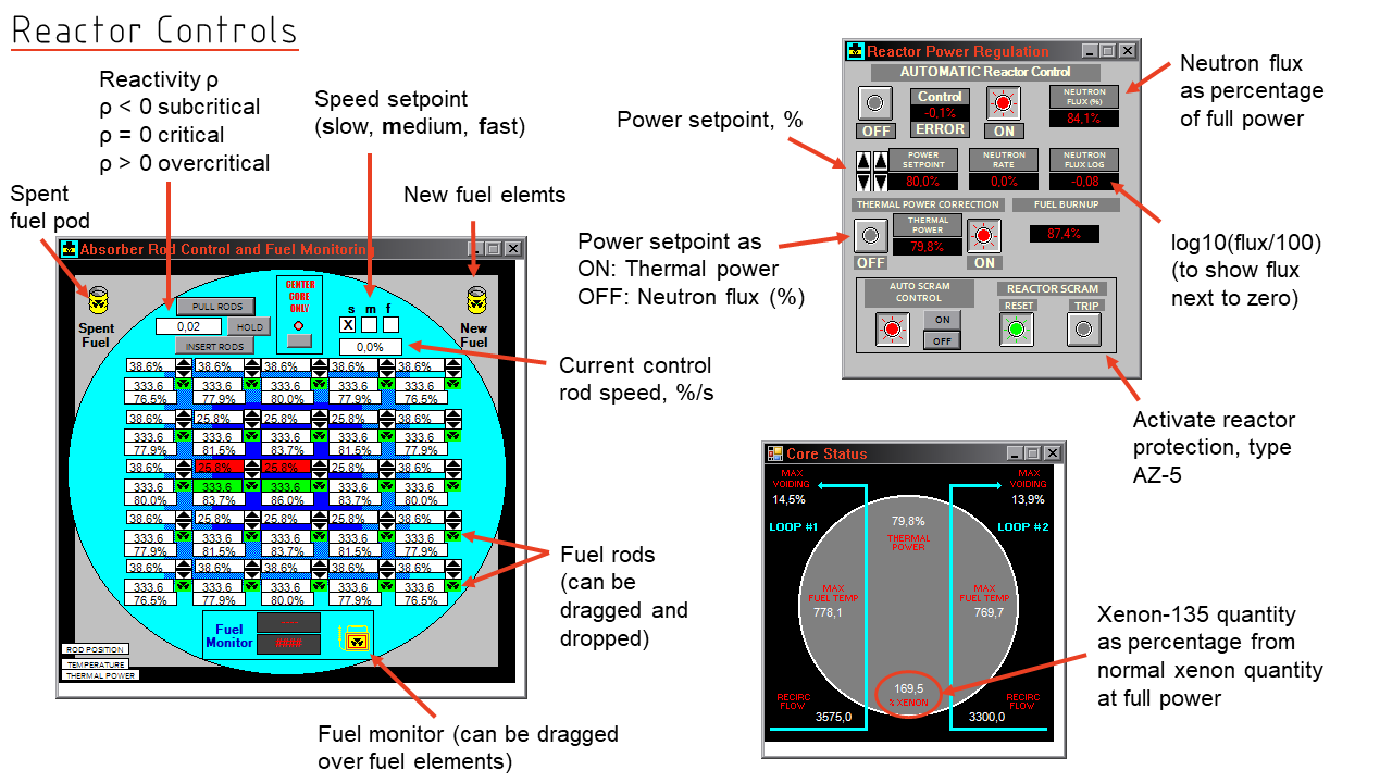
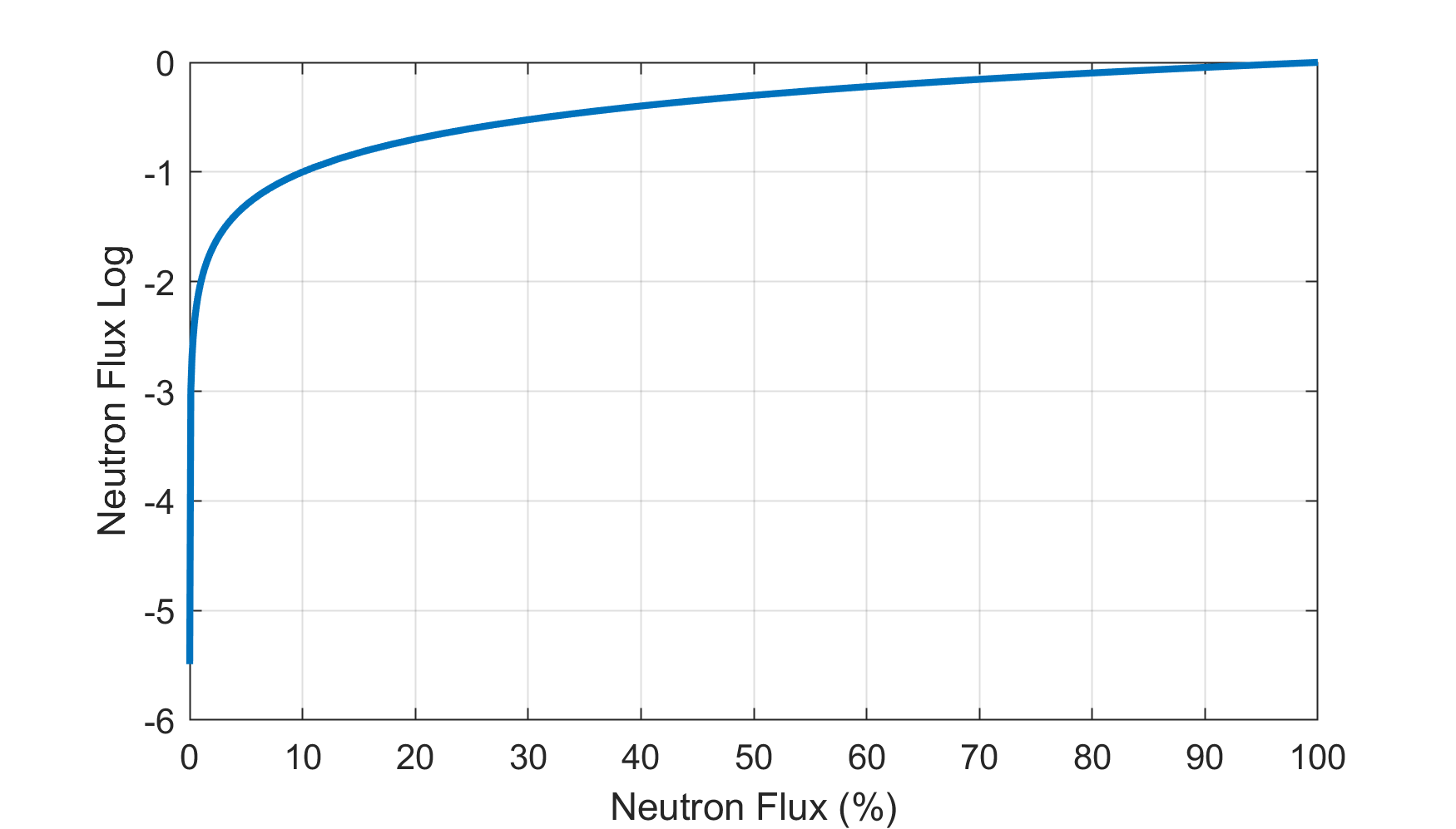
The power control displays the neutron flux and the 10 logarithm function of the neutron flux, calculated as log10(flux/100). The representation of the logarithm is used to indicate numerically the first increase of the neutron flux at values next to 0.
The reactivity displayed on the control rods is kind of similar to the criticality, 0 means “critical” here, values above zero are supercritical. The reactor has a constant thermal power at a reactivity of 0, a reactivity above 0 leads to an increase in power.
The activity of the individual fuel assemblies can be displayed by dragging the gauge at the bottom of the ” Absorber Rod Control” window onto the respective fuel assembly. You can remove the fuel elements and drag them into the decay pool and also insert new fuel elements from the top right into the pressure tube. If you let go of the mouse in the wrong place, the fuel assemblies lie around openly and an alarm is triggered because of too high radioactivity. Unfortunately, dragging in this window often causes the simulator to crash or the window to freeze.
Xenon Poisoning
Xenon-135 is produced in a delayed manner as a decay product from iodine-135 (half-life 6.6 hours). It has a much larger neutron absorption cross-section than any other material present in the reactor; if it is present, the reactivity of the reactor drops sharply because the neutrons that contribute to nuclear fission are captured by xenon-135. Xenon-135 is converted to xenon-136 by neutron capture during operation, or it decays to cesium-135 with a half-life of 9.2 hours. Below a reactor power of 60%, there is a risk of “xenon poisoning.”
To solve the problem of xenon poisoning, you need to know the following at this point: The reactor has just been shut down when playing as a power plant manager. The solution to the xenon problem is so obvious that it has not even been considered in many discussions on the Internet. After the shutdown, iodine-135 decays and causes the increase of xenon-135. This is the reality, not only in RBMK reactors. One simply has to wait until no new xenon-135 is formed from iodine-135 and the xenon-135 has decayed into its decay products. The simulator precisely reproduces this decay.
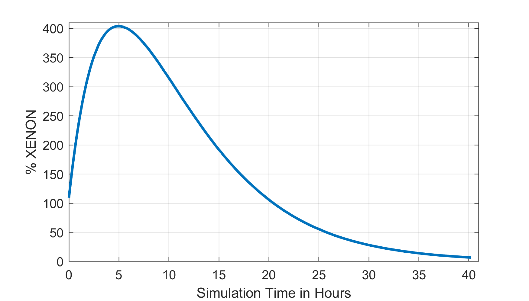
The xenon content increases in the first 5 hours to approx. 403.8 %. From approx. 230 %, startup is no longer possible. It then takes at least 20 hours until the reactor can be started up again. Of course, one can try to start the simulator at full load within the first half hour, but this procedure is not possible in reality.
However, due to the lack of a save function in the simulator, it is difficult to wait 30 hours or more with the start-up and then restart the start-up due to a turbine damage. Practically, however, this is possible if the simulator is operated in a virtual machine, but then other components must also be taken into account (e.g. replacing the HEPA filter).
To simplify the whole thing a bit and to save the waiting time, here is now an ICD fix where this decay had already taken place, because it is relatively annoying to have to wait 40 hours.
ICD-Fix
The ICD file downloadable here has a condition that may be typical for such a plant after a longer downtime due to repair
- No further xenon build-up, iodine-135 and xenon-135 have decayed as far as possible
- Make-up storage tank 2 filled to 71 %
- Low hotwell and deaerator storage levels
- HEPA filter replaced
- Rupture disc repaired
- Reactor temperature 41.5 °C, offline cooling and one circulation pump each active
- Deaerator vent valve already opened to 50% (manual opening costs many mouse clicks and time)
- Various systems are not on automatic mode
- Both feedwater de-mineralization trains are fully regenerated
Download the file here:
In practice, of course, any other constellations are conceivable – here you should have a condition in which you have to consider many plant components during startup and yet you don’t need to operate under time pressure.
I created the ICD file with the modified simulator version of Itchy-Avocado found on Reddid, here the save and repair function in the .exe was unlocked again.
More hints about the simulator operation
Aggregates and plant components are often controlled as a group, the designation of the control is “IN” for “In Service” and “OUT” for “Out of Service”. Red means “active”, green means “ready”.
Pumps are always started against a closed discharge valve and stopped with the discharge valve closed. Otherwise, there is a risk that a reverse flow will drive the pump and the pump will rotate backwards. A large asynchronous electric motor simply connected to a high voltage without an inverter or other modern electronics can explode in such a case. Some pumps have valves on the suction and discharge side, on other pumps there is only a control valve, which may be controlled by an automatic system. The valves on the suction side can remain open, the slide valves on the pressure side have to be closed before the pump is stopped, opened after the pump is started and must be closed before the pump is started. This is not always explicitly mentioned in the start-up instructions, but must always be done exactly this way.
There is no auxiliary steam. While many power plants use steam rails or auxiliary steam generators to provide the steam needed for some plant components during startup, we don’t have anything like that here. But that’s not actually a problem, since we can generate steam by using the reactor. You just have to know what you’re doing.
The decay heat is sufficient to heat up the reactor, to put the turbine’s barrier steam seal into operation and to operate the deaerator. However, permanent operation of the steam jet vacuum pumps of the condenser air ejector is not possible with the decay heat; the amount of steam generated is too small for this.
If all circulation pumps are off, no decay heat is simulated, even if circulation is provided by the decay cooling (Offline Cooling System). In order to simulate decay heat and cooling correctly, one circulation pump per circuit must be active.
During operation under full load, fuel elements are continuously changed; if this is not done, criticality may be lost. Unfortunately, this does not work flawlessly in the simulator.
Condenser vacuum is only possible with the help of the steam jet vacuum pumps, so an evacuation of the reactor to create a saturated steam condition before pressure build-up is not possible. If the rupture disc breaks due to the lack of vacuum, it can not be repaired.
The hotwell and the deaerator storage tank have a second, automatic valve, which prevents an overflow at a fixed value above the adjusted setpoint of the tanks when the control is active. For the hotwell, this valve opens at +5 above the adjusted setpoint.
Plant Step-by-Step Startup Procedure
The following instructions describe the individual steps, how I start the system from the above downloadable IC-State. It deviates in some places from the manual, I try to work as stable as possible and without load fluctuations.
Check safety systems: The emergency cooling valve (ECC or ERC) and the automatic reactor shutdown (Auto SCRAM Control) should be ready and enabled. The start-up process is not locked with these, but malfunctions or incorrect operation can quickly destroy the plant without these safety features.
Start up of a condeser circulating water pump: Cooling water is theoretically only needed when heat has to be removed from the condenser, in practice the main cooling water pumps can also feed cooling water subcircuits and hot, steaming condensate must also be able to be cooled immediately when it is discharged from the reactor, so this should be our first step to start up.
Place HEPA filter in service: Discharge air from the deaerator, feedwater treatment system and the core helium radiation detector must be filtered before being discharged to the environment to retain radioactive particles. Place the HEPA filter in service and close the bypass.
Fill hotwell: First, make sure that the hotwell level control is set to “Manual” and the auxiliary water valve to the hotwell is closed. Set the set point to “0”. If the control were active but there was no make-up water, the controller would open the valve completely. By the way, this behavior is completely normal and it is our task as operators to act accordingly here. We open the valve to the condensate storage tank 2 at “Makeup System”. We do not need the makeup water pumps because we have enough makeup water in the storage tanks. The flow valve control opens both the valve from the pumps to the tank and from the tank to the feed water system. After the flow valve on the cold condensate tanks is opened, carefully open the hotwell make-up water valve slightly and fill the hotwell manually. When the level is close to the set level, the control can be set to “Automatic”. I do not recommend filling an empty hotwell by putting the control on automatic mode, as this will cause a major overshoot. The hotwell level can only be lowered by using a condensate pump, but this has not yet been put into operation, as the hotwell initially still contains too little water for safe operation of those pumps.
Starting up the condensate system: Once the hotwell has been filled and the supply of make-up water has been ensured, the condensate system can be started up. It must first be ensured that the condensate control valve to the feedwater tank (DA) is closed and the control is set to Manual. If this is the case, a condensate pump can be switched on. If the condensate pump is active, one of the two streets of the condensate treatment system (polisher) is put into operation.
Filling the deaerator storage tank: The deaerator storage tank should also be filled carefully by hand, as the hotwell control tends to overshoot with such quantities of water. To do this, set the DA level setpoint to “0” and open the DA flow valve manually without switching to automatic mode. The set point also controls the overflow. Once the tank is filled, switch the control to automatic. The deaerator steam supply remains closed and out of operation at this time.
Turbine preparation: Hydraulic and lube oil pumps have to be switched on, the drains (Steam Drain) need to be opened. The steam seal valve remains closed. If hydraulic and lube oil pressure is present, the turbine controller can be reset (Turbine Trip Reset) and the turbine is switched to turning gear, the turbine should now turn slowly.
Preparations on the water-steam circuit: The reactor drain control is set to a setpoint of +4.0 and set to automatic mode. The setpoint must be higher than the level setpoint of the feedwater control, otherwise both control loops can control to the same target and the drain valve may not close. The steam dump valve is set to a setpoint of 11,500 kPa, closed and the control set to “Manual”. It is essential that the valve is closed. If the steam dump valve would open without a vacuum in the condenser, the rupture disc will break. The deaerator steam supply must also be closed and the control set to Manual. The deaerator vent will be opened to 50% (this is already done in the ICD file) and the pressure set point is set to 150 kPa.
Feed reactor: The feedwater control must be set to Manual and both the start-up and full-load feedwater valves must be closed. One feedwater pump can now be started up. The feedwater control is set to a setpoint of 0.0 withouth the three-element-control and the the start-up control valve will be selected. Once the feedwater pump is in service, the control will be set to automatic and the steam drum is now filled by the control.
We can now begin to heat the system.
At this point I like to change the trend display selection and show the following data: Drum pressure (green), Deaerator pressure (gray), Turbine speed (light green), Average control rod positions (blue-gray).
The following steps are not described like this in the manual. They represent my personal procedure for starting up the plant, with the aim of heating up the plant as evenly as possible with as few load changes as possible through controller interventions. First, the steam generation is ramped up to the appropriate parameters and operated in bypass mode (putting everything throuth the steam dump), then the turbine is warmed up and the steam is gradually fed over the turbine instead of through the steam dump.
Switch off off-line core cooling system: For this purpose, the circulation pumps of the offline cooling are switched off and the cooling water supply through the heat exchangers (Cooling Flow) is set to 0. On this occasion, all suction-side slide valves of the main circulation pumps can also be opened to have them ready later. With the offline cooling system switched off, the temperature in the reactor will now begin to rise slowly. The formation of steam bubbles and the expansion of the water will cause the level in the steam drum to rise and hot water must be drained into the hotwell. Discharging into the hotwell is done automatically by the reactor drain control system, and the water produced is automatically discharged from the hotwell when a level of 5 meters above setpoint is reached.
Vent and heat up the feed water: The steam supply to the deaerator will now be opened manually to approx. 15 to 20 % to allow the upcoming steam vapor to flow through the primary steam line to the deaerator storage tank. In this way, large steam lines can be preheated, air in the feedwater will be removed, and the steam supply to the deaerator storage tank heats up the feedwater. As soon as the temperature in the reactor reaches 100 °C, the steam starts to flow through the deaerator. The condensate produced here can be returned to the reactor or steam drum by manually opening the feedwater start-up control valve to approx. 5 % (the feed water control needs to be set to manual for this). This will also slow down the heating process a litte because we’re adding cold water to the reactor.
The reactor is warmed up with the decay heat until the first steam vapors will flow into the deaerator, beginning at 100 °C
From now on, two things must be observed during all further processes: As soon as the expansion of water and steam decreases and more steam leaves the reactor than is replenished (the feedwater control is still set to Manual at this point), the feedwater control must be switched to Automatic. If the pressure in the deaerator reaches the target setpoint of 150 kPa, the deaerator pressure control must be switched to Automatic. It helps to keep an eye on the trend lines (red represents the steam drum level and gray for the deaerator pressure) and the position of the reactor drain valve.
Reactor: The control rods are now used to manually ramp up the reactor to a neutron flux of 4 %. The setpoint control is set to the target setpoint of 4 %. For start-up, only the inner control rods will be pulled out. The control rods can be pulled out quickly in the beginning. When a neutron flux rate of approx. 3-4 % is reached, the speed must be reduced or the rod pull must be interrupted. The control rods are pulled out up to a reactivity of approx. max 0.4. While the reactivity is positive, the neutron flux and the thermal power will increase, as the reactor is supercritical. The reactivity must be lowered again in time, with the goal of reaching the 4 % neutron flux at a reactivity of 0 again at the same time. Experience shows that at a neutron flux of 3 % the reactivity should only be about 0.2 and then be lowered to 0 quite quickly. When the neutron flux reaches 4 %, the automatic reactor control is switched on and takes over the control of the control rods from here on. It is possible that the neutron flux will rise above 5 % if the reactivity has not been reduced in time. In this case, the control must be taken out of operation and the control rods must be pushed in a little. The control can then immediately be switched back to automatic. The procedure requires some practice.
There should now soon be a fast increase of pressure in the deaerator and the pressure control can be switched to automatic.
Evacuate condenser: As soon as pressure of 3300 kPa is reached, the steam seal can be put in operation. If there is sufficient pressure on the steam seal (approx. 29 kPa), the vacuum breaker can be closed and the steam jet vacuum air ejector pump can be used to evacuate the condenser. The steam jet air ejector vacuum pumps require a considerable amount of steam.
Operate the plant in steam bypass mode: As soon as the vacuum is available, the steam dump valve is opened manually to 10 % at a moderate speed. The target is to set the main steam pressure to a constant and stable value at approx. 7,500 to 8,500 kPa. The high steam extraction causes the steam drum level to drop. If the steam drum level approaches the setpoint of the feedwater controller (0.0), the feedwater control must be switched to automatic. It is not dramatic if the valve closes completely in the meantime before reaching the setpoint.
It is possible that the main steam dump valve must be opened up to 15% to keep the pressure stable, in this case the reactor power setpoint must be reduced by 0.5% and a lower reactor power setpoint must be used to try to get to this state. The reasons for this are that otherwise the feed water quantity of the start-up control valve of the feed water system will no longer be sufficient.
After a short time without oscillations, the plant should now be in a stable state (10 % steam dump valve opening, 4 % neutron flux setpoint) around 7,500 kP and 290 °C and the low main steam temperature warning should disappear. If this pressure setpoint has not yet been reached, the bypass control valve can be throttled back to 5 % for a time to increase the pressure in the reactor.
It is possible that the values described here are not exactly accurate and that a different condition is reached, but this is not a big deal. The steam just has to be hot enough and the system has to produce steam constantly without any surprises.
Turbine roll: Steam at a minimum temperature and pressure is required to roll the turbine. The manual recommends a pressure of 4480 kPa for starting up the turbine, but with the procedure described here, the pressure and temperature are already significantly higher. If the steam parameters are too low, damage will occur due to droplet formation, the turbine will vibrate unacceptably high and the process will take much longer. The power setpoint of the reactor control is now first increased from a target neutron flux from 4% to 5%. The pressure in the steam drum then continues to slowly increase. In this state, turbine rolling can be started; to do this, the turbine controller will be set to “Auto” and the target setpoint of 3,600 1/min is selected directly. In this state, it is possible to ramp up directly to the target speed at medium speed. The turbine will require steam during ramp-up, so the steam dump valve must be manually throttled so that the amount of steam required by the turbine does not flow through the steam dump valve, but the steam quantities extracted from the reactor remain the same in total. The valve is opened only enough to allow a further pressure rise in the reactor while the turbine is heating up. A pressure drop or rise is thus controlled accordingly with the steam dump valve position by hand, while the turbine takes the amount of steam it needs. The pressure at the end of the turbine ramp-up should be approximately between 9,000 and 10,000 kPa. When the holding speed is reached, the turbine valve will close somewhat, and the steam dump valve must be opened again accordingly. At the end, the steam dump valve is opened to approx. 7 %, and the turbine requires a steam quantity of 13 to 14 kg/s to maintain its speed.
Synchronize generator to grid: When the target speed is reached, the synchronization scope can be switched on. The turbine control holds the turbine at rated speed and is switched to pressure control when the generator switch is closed, the turbine valve then controls the main steam pressure. In the event of adverse pressure fluctuations, the valve may close completely, causing turbine ventilation because the turbine is driven by the generator and this will trigger turbine fast trip. The following steps are taken in direct and rapid succession to prevent generator motor operation and turbine ventilation: The turbine controller is switched to Manual, thus the turbine valve is no longer controlled but stays in correct position. The prerequisite for this is a stable plant without rapid load fluctuations, which should have been guaranteed up to now. The generator breaker is closed as soon as the rotating fields match and then the turbine valve is immediately opened manually by a further 4-5 % to keep the generator under load. The steam dump valve can then immediately be switched to “automatic”, this will close the valve completely because of the high setpoint. The entire steam flow is now passed to the turbine, generating electricity, and the reactor power should remain stable at 5% neutron flux.
Behavior in the event of turbine fast shutdown: If, contrary to expectations, synchronization does not succeed and the turbine trips, it is only necessary to reopen the steam dump valve in order to continue taking steam from the reactor. It is messy if this happens through the control system, since the pressure will have risen a long way by then. Venting the radioactive steam through the safety valves must be avoided at all costs. It is more elegant to open the steam dump valve immediately when the turbine valves themselves are closed quickly to 12% and not to upset the steam generation control loops too much. It is also not a bad thing if the drum pressure drops slowly as a result; it can be increased again by lowering the position of the steam dump control valve.
The reactor pressure will increase after closing the steam dump valve, the turbine start-up valve needs to be opened further (to approx. 15 %).
The following controls are now changed over before a further power increase. After each step, wait briefly until the control circuits have settled again.
The feedwater drum level control is changed to three-element control and the main control valve is used.
The turbine controller is switched to automatic. When switching to automatic, the turbine controller will now adopt the current main steam pressure as a new setpoint and hold it.
The power setpoint of the reactor is now slowly increased to 8 %.
When the power setpoint of 8 % is reached, a pressure increase towards the target pressure of 10340 kPa is initiated. For this purpose, the pressure setpoint will be increased in steps of approx. 300 kPa. If the turbine control valve closes too much, the process must be interrupted and the valve must be operated manually. Ventilation of the turbine must be prevented at all costs.
Once the target setpoint is reached, we will switch to the main control valve of the turbine. The plant can now be further ramped up to full load via the reactor setpoint (but not above 100% neutron flux, this will terminate the simulation immediately!), during the ramp-up a few more things have to be done.
At a power setpoint of 25 %, it is possible to switch to thermal power control by turning on “thermal power correction”.
According to the manual, the turbine drains can be closed when the generator reaches an output of 80 MW.
Two reactor circulation pumps, two condensate pumps and two feedwater pumps are required for full-load operation. For condensate and feedwater pumps, an additional pump becomes necessary when the control valve reaches a position that is too large, i.e. must be opened too wide by the controller. Then the pressure of the pump is no longer sufficient. Here, one should not allow control valve positions above 60 % in order to have sufficient control reserve. The manual specifies that a second reactor circulation pump should be put in service at 250 MW.
The second condenser circulating water pump becomes necessary as soon as the pressure in the condenser starts to rise. If the heat is not sufficiently dissipated, the condenser pressure increases and the efficiency of the turbine decreases. This happens from about 450 MW.
*: Images contain copyrighted material which is protected by international copyright laws and is property of Simgenics. These images can not be used under certain licenses unlike other pictures on this blog.
Okay. This does really solve my problem.
But the xenon, Ugh.
I have been using the port version of this RBMK simulator, the one created by “gdzx” and posted on GitHub. It runs on my Windows 11 computer, but I can never manage to start up the reactor because there is too much xenon. If I try to let the xenon decay during many hours of simulator run time (with the reactor shut down and the offline cooling system running), I get problems with water quality. I tried using Cheat Engine to make the value of the xenon much smaller, but I can’t find any way to change the xenon value. I can’t seem to create a situation from which I can start the reactor in a straightforward way.
I would love to try using your file “chernobyl01.icd”, which you linked in this post, but I can’t get it to work with the port version of the simulator. Do you know if it would be possible to create a version of that file that would run with gdzx’s port of the simulator?
Hi, sorry, can’t help you with that. I used a Windows 7 x86 VM to run the simulation for hours and then used the reimplemented save feature. But actually I didnt have any issues with water quality. But it also works in windows 11, just some mior UI bugs after some time.
It seems I have made grosse Kacka on my first not-so-poisoned systartup attempt:
https://imgflip.com/i/9gkouq
https://i.imgflip.com/9gkoqs.jpg
Fuel temperature is at >20’0000°C and rising, doesn’t register as a meltdown somehow – not great, not terrible.
Would you be able to post the file download for the windows 10 version? I can’t find it on the simgenics site, thanks.
It got taken off the website, but here’s a Dropbox mirror: https://www.dropbox.com/s/mff1ms4w05fqywb/CHRNOBYL.rar?dl=0
Thank you for the very detailed information, and the version of the plant schematic that you have constructed.
I was wondering, do you have a higher resolution version? I’d like to print it out in A3 for my wall near my Windows 95 computer (where I have the full simulator).
I’ve been going through the manual scan that is available and I’ve been cropping and making it grey scale so I can print it in an A5 book that I’ll put on my website for anyone else that wants a copy that’s easier to print. I’ve also added OCR to the PDF so parts of it can be copied – I may even design a new book with the original text and illustrations so it looks nice, either way I’ll put it on my site, as well as with all the versions of the simulator I’ve found and the knowledge I’ve managed to find.
Would you mind if I put your schematic on the site too? I’d link back to your site of course, as well as to your experience with the simulator 🙂
Kind regards,
Jessica (aka jcx)
Hi jcx, there’s a pdf version for download available which should contain printable vector graphics but anyway, here is the original svg file I exported the schematics from: https://hartrusion.com/uploads/rbmk-simulator-pid-schematic.svg . You can also hide the description layers there if you do not want to print them. I used Inkscape to create the file. This svg should allow you to print in a decent quality.
It is an honor if someone uses or extends the content from my small blog here, I try to make everything available under cc by sa licence but in this case it might be a derived work. I actually asked at Simgenics before publishing this blog post here and got a really nice answer from them. So, for my part I’m totally fine if you put the schematic on your site with a backlink (thanks for a link anyway!) but I can’t officially license it. Unfortunately they seem to have removed the simulator from their page. Maybe you can just contact them, they have invested lots of time and effort when creating this thing decades ago and seem to be very pleased that people now like that product.
The manual itself is quite a nice piece of literature, as former power plant engineer I can tell that it is really accurate and informative, as well as the whole simulator.
thanks for your comment and best regards, viktor
Hi Viktor,
Thank you 🙂
Yes, I would have thought it’d count as derivative work so I completely understand 🙂
Often with works like this I generally (perhaps wrongly!) think that it’s okay so long as it’s not being done for profit and the original author(s) are credited appropriately then it’s generally “okay” (I’d feel the same about any of my works from years ago, especially if I didn’t have them for sale any more). It’d be awesome if the company released a new version of the software for later operating systems.
I have a quad monitor setup here, and I’m working on ways to get each of the controls distributed over them (given that the main panel in the simulator is mostly decorative (except in the demos that people have made where some of the readouts are displayed!).
I decided to redo the manual (as a reproduction) using a couple of free fonts that are pretty close to the original, and try and get better (either colour, or higher resolution) pictures and diagrams. I tried to clean up the manual scan that someone had graciously sat and scanned but there’s a lot of things that make it look bad printed, like some of the pages are quite skewed or the paper got ruffled so the text is kinda wavy… and I’d just like a decent printed manual – since as you say, it’s very good. Not impenetrable to someone who knows nothing about a nuclear reactor, but will also add important information for those experienced (but perhaps not with an RBMK!)
In the spirit of the small community of RBMK reactor “enthusiasts” (would that be an appropriate name for us?) I’ll put it on my site, just in case anyone wants a printed manual when I’ve finished it. I’ve tried to find an original copy on-line without luck. I kinda wish they were still selling them, because you’re right that they put an incredible amount of effort into the game and it’s a shame it’s not on their site any more.
I had to laugh playing with the simulator (I’m still quite new to it) and caused a meltdown, but the message when that happens had me in stitches. “You have caused a meltdown. Try again.” – it sort of reminded me of that Simpsons episode where Homer said “It’s my first day” 🙂
Thanks again for the vector version of your schematic, I really appreciate it. Think it’ll make a great wall piece near my old computers 🙂
Kind regards,
Jessica (jcx)
Hello Viktor, you did a great job at describing the simulator with much higher detail than the users manual itself. And thanks for mentioning my Youtube video in the post!
Thanks a lot for your video, without your work I would not even know that this thing existed! I highly appreciate your work and your publications regarding that simulator, it is of great help.